
Technical data


54 • Fieldbus Controller 750-841
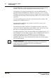
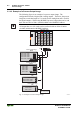
Process Image
WAGO-I/O-SYSTEM 750
ETHERNET TCP/IP
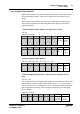
Output Process Image
Bit 7 Bit 6 Bit 5 Bit 4 Bit 3 Bit 2Bit 1Bit 0
controls
DO 2
Channel
2
controls
DO 1
Channel
1
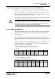
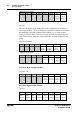
750-506
The 750-506 digital output module has 2-bits of diagnostic information for
each output channel. The 2-bit diagnostic information can then be decoded to
determine the exact fault condition of the module (i.e., overload, a short
circuit, or a broken wire). The 4-bits of diagnostic data are mapped into the
Input Process Image, while the output control bits are in the Output Process
Image.
Input Process Image
Bit 7 Bit 6 Bit 5 Bit 4 Bit 3 Bit 2 Bit 1 Bit 0
Diagnosti
c bit S 3
Channel 2
Diagnosti
c bit S 2
Channel 2
Diagnosti
c bit S 1
Channel 1
Diagnosti
c bit S 0
Channel 1
Output Process Image
Bit 7 Bit 6 Bit 5 Bit 4 Bit 3 Bit 2 Bit 1 Bit 0
not used not used
controls
DO 2
Channel
2
controls
DO 1
Channel
1
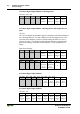
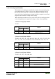
4 Channel Digital Output Modules
750-504, -516
Bit 7 Bit 6 Bit 5 Bit 4 Bit 3 Bit 2 Bit 1 Bit 0
controls
DO 4
Channel
4
controls
DO 3
Channel
3
controls
DO 2
Channel
2
controls
DO 1
Channel
1
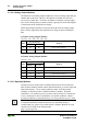
8 Channel Digital Output Module
750-530
Bit 7 Bit 6 Bit 5 Bit 4 Bit 3 Bit 2 Bit 1 Bit 0
controls
DO 8
Channel
8
controls
DO 7
Channel
7
controls
DO 6
Channel
6
controls
DO 5
Channel
5
controls
DO 4
Channel
4
controls
DO 3
Channel
3
controls
DO 2
Channel
2
controls
DO 1
Channel
1