
Technical data


Fieldbus Controller 750-841 • 53
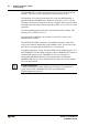
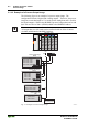
Process Image
WAGO-I/O-SYSTEM 750
ETHERNET TCP/IP
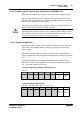
3.1.4.3.2 Digital Output Modules
Digital output modules use one bit of data per channel to control the output of
the corresponding channel. These bits are mapped into the Output Process
Image.
When analog output modules are also present in the node, the digital image
data is always appended after the analog data in the Output Process Image,
grouped into bytes.
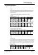
1 Channel Digital Output Module with Input Process Data
750-523
Input Process Image
Bit 7 Bit 6 Bit 5 Bit 4 Bit 3 Bit 2Bit 1Bit 0
not used
Status bit
„Manual
Operatio
n“
Output Process Image
Bit 7 Bit 6 Bit 5 Bit 4 Bit 3 Bit 2Bit 1Bit 0
not used
controls
DO 1
Channel
1
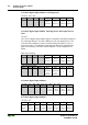
2 Channel Digital Output Modules
750-501, -502, -509, -512, -513, -514, -517, -535
Bit 7 Bit 6 Bit 5 Bit 4 Bit 3 Bit 2Bit 1Bit 0
controls
DO 2
Channel
2
controls
DO 1
Channel
1
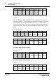
2 Channel Digital Input Modules with Diagnostics and Input Process
Data
750-507, -522
The 750-507 and 750-522 digital output modules have a diagnostic bit for each
output channel. When an output fault condition occurs (i.e., overload, short
circuit, or broken wire), a diagnostic bit is set. The diagnostic data is mapped
into the Input Process Image, while the output control bits are in the Output
Process Image.
Input Process Image
Bit 7 Bit 6 Bit 5 Bit 4 Bit 3 Bit 2 Bit 1 Bit 0
Diagnosti
c bit S 2
Channel 2
Diagnosstic
bit S 1
Channel 1