
Technical data


Fieldbus Controller 750-841 • 43
Hardware
WAGO-I/O-SYSTEM 750
ETHERNET TCP/IP
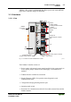
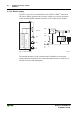
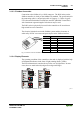
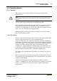
3.1.2.6 Operating Mode Switch
The operating mode switch is located behind a cover flap.
Mode switch
UPDATE FIRMWARE
RUN
STOP
RESET
(pushing down)
Fig. 3-4: Operating Mode Switch g01xx10e
The switch is a push/slide switch with 3 settings and a hold-to-run function.
The slide switch is designed for a maximum number of switching cycles as
defined in EN61131T2.
Operating mode switch Function
From middle to top position Firmware and PFC application are executed (Activate
program processing (RUN)
From top to middle position Firmware is executed, PFC application is stopped (Stop
program processing (STOP)
Lower position, bootstrap Controller starts the operating system loader
Push down
(i.e. with a screwdriver)
Hardware reset
All outputs and flags are reset; variables are set to 0 or to
FALSE or to an initial value.
Retain variables or flags are not changed.
The hardware reset can be performed with STOP as well
as RUN in any position of the operating mode switch!
An operating mode (i.e., RUN/STOP) is internally changed at the end of a
PLC cycle.
Note
The position of the mode switch is not important when starting or stopping
the PFC application from WAGO-I/O-PRO.