
Technical data


36 • Fieldbus Controller
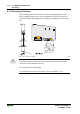
Fieldbus Controller 750-841
WAGO-I/O-SYSTEM 750
ETHERNET TCP/IP
3 Fieldbus Controller
3.1 Fieldbus Controller 750-841
This chapter includes:
3.1.1 Description...................................................................................... 38
3.1.2 Hardware......................................................................................... 39
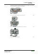
3.1.2.1 View.........................................................................................39
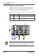
3.1.2.2 Device Supply.......................................................................... 40
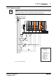
3.1.2.3 Fieldbus Connection ................................................................ 41
3.1.2.4 Display Elements ..................................................................... 41
3.1.2.5 Configuration and Programming Interface .............................. 42
3.1.2.6 Operating Mode Switch ........................................................... 43
3.1.2.7 Hardware Address (MAC-ID).................................................. 44
3.1.3 Operating System............................................................................ 45
3.1.3.1 Start-up..................................................................................... 45
3.1.3.2 PLC Cycle ................................................................................ 45
3.1.4 Process Image ................................................................................. 47
3.1.4.1 Example of a Process Input Image...........................................49
3.1.4.2 Example of a Process Output Image........................................ 50
3.1.4.3 Fieldbus specific Process Data Architecture for MODBUS/TCP51
3.1.5 Data Exchange ................................................................................ 63
3.1.5.1 Memory Areas.......................................................................... 64
3.1.5.2 Addressing ............................................................................... 66
3.1.5.3 Data Exchange between MODBUS TCP Master and I/O
Modules.................................................................................... 69
3.1.5.4 Data Exchange between Ethernet IP Master and I/O Modules 71
3.1.5.5 Data Exchange between PLC Functionality (CPU) and I/O
Modules.................................................................................... 72
3.1.5.6 Data Exchange between Master and PLC Functionality (CPU)73
3.1.6 Starting up an ETHERNET TCP/IP fieldbus node......................... 78
3.1.6.1 Note the MAC-ID and establish the Fieldbus Node ................ 78
3.1.6.2 Connecting PC and Fieldbus Node.......................................... 79
3.1.6.3 Determining IP Addresses .......................................................79
3.1.6.4 Allocating the IP Address to the Fieldbus Node...................... 80
3.1.6.5 Testing the Function of the Fieldbus Node.............................. 83
3.1.6.6 Deactivating the BootP Protocol.............................................. 84
3.1.7 Programming the PFC with WAGO-I/O-PRO CAA...................... 85
3.1.7.1 WAGO-I/O-PRO CAA library elements for ETHERNET ...... 89
3.1.7.2 IEC 61131-3-Program transfer.................................................90
3.1.7.3 Information on the web-based management system ................ 93
3.1.8 LED Display ................................................................................... 96
3.1.8.1 Blink code ................................................................................ 96
3.1.8.2 Fieldbus status.......................................................................... 97
3.1.8.3 Node status............................................................................... 98
3.1.8.4 Fault Message via Blink Code from the I/O-LED ................... 99
3.1.8.5 ‘USR‘-LED ............................................................................100