
Technical data

100 • Fieldbus Controller 750-841
Fault behavior
WAGO-I/O-SYSTEM 750
ETHERNET TCP/IP
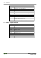
3.1.8.5 ‘USR‘-LED
The state of the ‘USR‘ LED is programmable with WAGO-I/O-PRO CAA.
Functions in the program library ”Visual.lib“ can be used to control the LED
state. One of the many possible uses of this LED is to indicate the RUN/STOP
state of your controller.
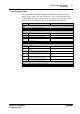
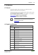
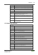
3.1.8.6 Supply voltage status
The two green LED’s in the controller supply section, display the status of the
supply voltage. The left LED (A) indicates the status of the 24 V supply for
the controller. The right LED (B or C) displays the status of the field side
supply (i.e., the power jumper contacts).
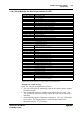
LED Meaning Trouble shooting
A
green Operating voltage for the system exists.
OFF No operating voltage for the system. Check the supply voltage (24V and 0V).
B or C
green Operating voltage for the power jumper contacts
exists.
OFF No operating voltage for the the power jumper
contacts.
Check the supply voltage (24V and 0V).
3.1.9 Fault behavior
3.1.9.1 Fieldbus failure
When a Modbus TCP fieldbus failure occurs (e.g., the Ethernet cable is
removed or broke), the outputs that are controlled by the fieldbus port remain
in their current state by default. If this behavior is undesirable, a fieldbus
watchdog timer can be programmed to monitor Fieldbus communications.
The watchdog monitors the data transfer between the master controls and the
PFC. In the event of a watchdog timeout (i.e., there is a Fieldbus failure), the
PFC can be programmed to control the state of the outputs, based on your
application needs. In the case of fault free communications, the watchdog
timer will not timeout, since after each successful data transfer the watchdog
timer is reset.
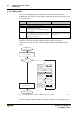
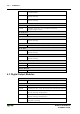
Monitoring the watchdog time in the PFC is done by using the function block
'FBUS_ERROR_INFORMATION' in the control program. This function is
part of the “mod_com.lib” library.
Fig. 3-16: Function block for determining a fieldbus failure g012926x