
Technical data

Fieldbus Controller 750-841 • 99
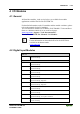
LED Display
WAGO-I/O-SYSTEM 750
ETHERNET TCP/IP
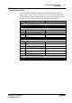
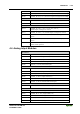
3.1.8.4 Fault Message via Blink Code from the I/O-LED
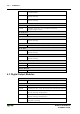
Fault argument Fault description
Fault code 1: Hardware and Configuration fault
1 Overflow of the internal buffer memory for the inline code
2 Unknown data type
3 Checksum error of the parameter data
4 Acknowledge Fault when writing data in the EEPROM
5 Fault when reading out data from the EEPROM
6 Changed I/O module configuration determined after AUTORESET
7 Firmware does not run on existing hardware
8 Timeout when writing data in the EEPROM
9 Bus Controller initialisation fault
10 RTC-Powerfail
11 Fault when reading out the time from the RTC
12 Fault when writing the time in the RTC
13 Error Clock-Interrupt
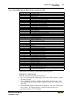
Fault code 2: Fault in programmed configuration
1 Process image not actively when switching control or monitor mode
2 Process image is too large for the existing buffer
3 Fault when compiling the process image
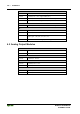
Fault code 3: Internal bus command fault
0 No fault argument is put out.
Fault code 4: Internal bus data fault
0 Data fault on internal bus or
Internal bus interruption on controller
n* (n>0) Internal bus interrupted after I/O module n
Fault code 5: Fault during register communication
n* Internal bus fault during register communication after I/O module n
Fault code 6: Fieldbus specific errors
1Invalid MACID
2 Ethernet Hardware initialization error
3 TCP/IP initialization error
4 Network configuration error (no IP Address)
5 Application protocol initialization error
6 Process image is too large
7 Double IP address in network
8 Error when building the process image
Fault code 7: I/O module is not supported
n* I/O module at position n is not supported
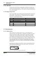
Fault code 8: not used
0 Fault code 8 is not used.
Fault code 9: not used
0 Fault code 9 is not used.
Fault code 10: PFC error
1 Error when implementing the PFC run time system
2 Error when generating the PFC inline code
3 An IEC task exceeded the maximum running time or the sampling interval of the
IEC task could not be kept (Watchdog)
* The number of blink pulses (n) indicates the position of the I/O module. I/O modules
without data are not counted (i.e. supply modules without diagnostics).
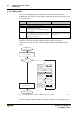
Example for a fault message
Fault: The 13th I/O module has been removed
1. The "I/O" LED starts the fault display with the first blink sequence (approx.
10 flashes/second).
2. The second blink sequence (1 flash/second) follows the first pause. The
"I/O" LED blinks four times and thus signals the fault code 4 (internal bus
data fault).
3. The third blink sequence follows the second pause. The "I/O " LED blinks
twelve times. The fault argument 12 means that the internal bus is
interrupted after the 12
th
I/O module.