
Technical data


96 • Fieldbus Controller 750-841
LED Display
WAGO-I/O-SYSTEM 750
ETHERNET TCP/IP
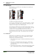
3.1.8 LED Display
The controller has several LED’s for a visual display of the controller and
nodes operating status.
24V 0V
++
01
02
LINK
MS
NS
I/O
ETHERNET
C
D
B
A
TxD/RxD
USR
C
B
A
24V 0V
++
01
02
LINK
MS
NS
I/O
ETHERNET
C
D
B
A
TxD/RxD
USR
C
B
A
C
A
24V 0V
++
01
02
LINK
MS
NS
I/O
ETHERNET
C
D
B
A
TxD/RxD
USR
C
B
A
A
B
C
A
Fig. 3-14: Display elements 750-841 g084102x
The LEDs can be divided into three groups.
The first group of LEDs display the status of the Ethernet fieldbus. It contains
both solid and two-color LEDs. They are labelled as: ‘LINK‘ (green), ‘MS‘
(red/green), ‘NS‘ (red/green), and ‘TxD/RxD‘ (green).
The second group of LEDs are three-color LEDs (red/green/orange). One of
the LED is labelled ‘I/O’, and displays the status of the internal bus. The other
is labelled ‘USR’, and is programmable with WAGO-I/O-PRO CAA.
The third group uses solid colored LEDs. They are located on the right-hand
side of the controller power supply. These display the status of the supply
voltage.
3.1.8.1 Blink code
When the PFC is in a faulted, the ‘I/O’ LED is used to signal the fault type
through a series of flashes (i.e., blink code). The blink code is cyclically
displayed using 3 different blink sequences.
• The first blink sequence (approx. 10 flashes/second) indicates the start of a
new sequence.
• After a pause, a second blink sequence starts (approx. 1 flash/second).
Count the number of flashes to determine the fault code (e.g., 3 flashes
equals Fault Code 3).
• The third blink sequence (approx. 1 flash/second) starts following a another
pause. Count the number of flashes to determine the fault argument.