
Technical data


70 • Feldbus Coupler 750-344 / -345
LED Indication
WAGO-I/O-SYSTEM 750
INTERBUS
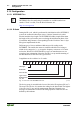
3.1.7 LED Indication
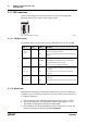
For the on-site diagnostics the coupler has five LEDs, which display the
operating status of the coupler or the complete node.
Fig. 3-10: Indicators 750-344 g012232x
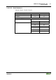
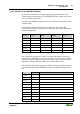
3.1.7.1 Fieldbus status
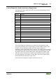
The fieldbus status is indicated by the four LEDs READY, BA, RC and RD:
LED Color Status Meaning
READY
Ready for
operation
green ON
OFF
Power supply within acceptable tolerance range,
device is ready for operation
Device not ready for operation, insufficient power
supply
BA
Bus Active
green ON
BLINKS
OFF
Bus is active, data transmission taking place
INTERBUS controller has active configuration,
data transmission not yet started
Bus not active, no data transmission
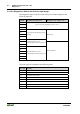
RC
Remote
Connected
green ON
OFF
Incoming interface connected, bus reset for master
is inactive
Bus reset is active, or interface not connected
properly
RD
Remote
Disconnected
yellow ON
OFF
Transferring remote bus (outgoing interface) de-
activated
Transferring remote bus not in use or not switched
on
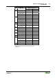
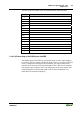
3.1.7.2 Blink Code
Detailed error messages are indicated by blinking codes; an error is indicated
cyclically by up to 3 blinking sequences. An error is indicated cyclically by up
to 3 blinking sequences.
The error display starts with the first blinking sequence (approx. 10 Hz).
After a short break, the second blinking sequence starts (approx. 1 Hz).
The number of light pulses indicates the error code.
After another break, the third blinking sequence starts (approx. 1 Hz). The
number of light pulses indicates the error argument.