
Technical data

Feldbus Coupler 750-344 / -345 • 53
Process Image
WAGO-I/O-SYSTEM 750
INTERBUS
3.1.4 Process Image
3.1.4.1 Local Process Image
After being switched on, the coupler identifies all I/O modules connected that
supply or are expected to receive process data (data width or bit width > 0). In
nodes analog and digital I/O modules can be fitted mixed.
NOTE:
For the number of input and output bits and bytes of the individual connected
I/O modules, please see the corresponding descriptions of the I/O modules.
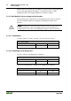
The coupler creates a local process image on the basis of the data width, the
type of I/O module and the position of the module in the node. This is divided
into an input and an output area.
For both the local input and the output process image, I/O module data is
stored in the corresponding process image. This is based on the order in which
the modules are connected to the coupler.
The data of the word-oriented modules (analog modules and specialty
modules) are stored first in the process image. The bits of the bit-oriented
(digital) modules are sent byte by byte and added to the analog data. If the
amount of digital information exceeds 8 bits, the coupler automatically starts
with a new byte.
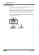
3.1.4.2 Allocation of the Input and Output Data
The process data is exchanged via the INTERBUS with the higher ranking
controls (master). The maximum data width in the input and output process
image is 20 bytes.
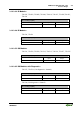
The process image is broken down into input and output data through the
internal structure of the INTERBUS coupler.
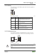
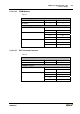
Input data
E0
|
E
n
word-oriented data
E
n+1
|
E
n+m
bit-oriented data
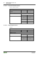
Output Data
A0
|
A
n
word-oriented data
A
n+1
|
A
n+m
bit-oriented data