
Technical data

Feldbus Coupler 750-344 / -345 • 51
Hardware
WAGO-I/O-SYSTEM 750
INTERBUS
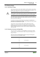
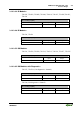
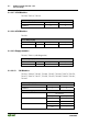
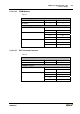
3.1.2.4 Indicators
The operating status of the fieldbus couplers and of the node is signaled via
light diodes (LEDs).
Fig. 3-5: Indicators 750-344 g012232x
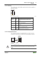
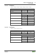
LED Color Meaning
READY green The READY LED shows the status for power
supply and the operational readiness of the
coupler.
BA green The BA LED shows that the bus is active, with
data transfer taking place.
RC green The RC LED shows the status of the incoming
interface.
RD yellow The RD LED shows the status of the transferring
remote bus (outgoing interface).
I/O red /green
/ orange
The "I/O" LED indicates both the internal bus
communication and occurring errors.
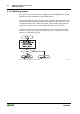
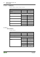
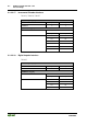
3.1.2.5 Configuration Interface
The configuration interface is located behind the cover flap. It is used to
communicate with WAGO-I/O-CHECK and for transmitting of firmware.
Configuration
interface
open
flap
Fig. 3-6: Configuration interface g01xx06e
Notice!
Only the communication cable (750-920) may be connected to the 4-pole
header.