Modular I/O system INTERBUS 750-344, 750-345 Manual Technical Description, Installation and Configuration Version 1.0.
ii • General Copyright 2002 by WAGO Kontakttechnik GmbH All rights reserved. WAGO Kontakttechnik GmbH Hansastraße 27 D-32423 Minden Phone: +49 (0) 571/8 87 – 0 Fax: +49 (0) 571/8 87 – 1 69 E-mail: info@wago.com Web: http://www.wago.com Technical Support Phone: +49 (0) 571/8 87 – 5 55 Fax: +49 (0) 571/8 87 – 85 55 E-mail: support@wago.com Every conceivable measure has been taken to ensure the accuracy and completeness of this documentation.
Table of Contents • iii TABLE OF CONTENTS 1 Important Notes ......................................................................................... 5 1.1 Legal Bases ............................................................................................ 5 Standards and Guidelines for Operating the 750 Series ........................ 7 1.2 1.3 Symbols ................................................................................................. 8 1.4 Safety Information ...........................
iv • Table of Contents WAGO-I/O-SYSTEM 750 INTERBUS
Important Notes Legal Bases • 5 1 Important Notes This section includes an overall summary of the most important safety requirements and notes that are mentioned in each individual section. To protect your health and prevent damage to devices as well, it is imperative to read and carefully follow the safety guidelines. 1.1 Legal Bases 1.1.1 Copyright This Manual, including all figures and illustrations, is copyright-protected.
• Important Notes Legal Bases All responsible persons have to familiarize themselves with the underlying legal standards to be applied. WAGO Kontakttechnik GmbH & Co. KG does not assume any liability whatsoever resulting from improper handling and damage incurred to both WAGO´s own and third-party products by disregarding detailed information in this Manual. 1.1.
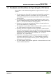
Important Notes Standards and Guidelines for Operating the 750 Series • 7 1.2 Standards and Guidelines for Operating the 750 Series Please adhere to the standards and guidelines required for the use of your system: The data and power lines shall be connected and installed in compliance with the standards required to avoid failures on your system and to substantially minimize any imminently hazardous situations resulting in personal injury.
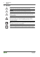
• Important Notes Symbols 1.3 Symbols Danger Always observe this information to protect persons from injury. Warning Always observe this information to prevent damage to the device. Attention Marginal conditions that must always be observed to ensure smooth and efficient operation. ESD (Electrostatic Discharge) Warning of damage to the components through electrostatic discharge. Observe the precautionary measure for handling components at risk of electrostatic discharge.
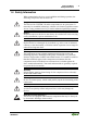
Important Notes Safety Information • 9 1.4 Safety Information When connecting the device to your installation and during operation, the following safety notes must be observed: Danger The WAGO-I/O-SYSTEM 750 and its components are an open system. It must only be assembled in housings, cabinets or in electrical operation rooms. Access is only permitted via a key or tool to authorized qualified personnel.
• Important Notes Font Conventions Warning For components with ETHERNET/RJ-45 connectors: Only for use in LAN, not for connection to telecommunication circuits. 1.5 Font Conventions italic Names of paths and data files are marked in italic-type. e.g.: C:\Programs\WAGO-IO-CHECK italic Menu items are marked in italic-type, bold letters. e.g.: Save \ A backslash between two names characterizes the selection of a menu point from a menu. e.g.
Important Notes Scope of Validity 1.7 Scope of Validity This manual outlines all the components for the fieldbus-independent WAGO-I/O-SYSTEM 750 with an INTERBUS-ECO fieldbus coupler. Item no. Description 750-344 INTERBUS-ECO Fieldbus coupler, 500 kBaud 750-345 INTERBUS-ECO Fieldbus coupler, 2 MBaud 1.
• The WAGO-I/O-SYSTEM 750 System Description 2 The WAGO-I/O-SYSTEM 750 2.1 System Description The WAGO-I/O-SYSTEM 750 is a modular, field bus independent I/O system. It is comprised of a field bus coupler/controller (1) and connected field bus modules (2) for any type of signal. Together, these make up the field bus node. The end module (3) completes the node. Fig.
30BTechnical Condition of Specified Devices Carrier Rail Properties • 13 2.2 Technical Data Mechanic Material Polycarbonate, Polyamide 6.
• The WAGO-I/O-SYSTEM 750 Technical Data Safe electrical isolation Air and creepage distance acc. to IEC 60664-1 Degree of pollution acc. To IEC 61131-2 2 Degree of protection Degree of protection IP 20 Electromagnetic compatibility Immunity to interference for industrial areas acc. to EN 61000-6-2 (2001) Test specification Test values Strength class Evaluation criteria EN 61000-4-2 ESD 4 kV/8 kV (contact/air) 2/3 B EN 61000-4-3 electromagnetic fields 10 V/m 80 MHz ...
30BTechnical Condition of Specified Devices Carrier Rail Properties • 15 Mechanical strength acc. to IEC 61131-2 Test specification Frequency range Limit value IEC 60068-2-6 vibration 5 Hz f < 9 Hz 1.75 mm amplitude (permanent) 3.5 mm amplitude (short term) 9 Hz f < 150 Hz 0.5 g (permanent) 1 g (short term) Note on vibration test: a) Frequency change: max.
• The WAGO-I/O-SYSTEM 750 Technical Data For Products of the WAGO-I/O-SYSTEM 750 with ship specific approvals supplementary guidelines are valid: Electromagnetic compatibility Immunity to interference acc. to Germanischer Lloyd (2003) Test specification Test values Strength class Evaluation criteria IEC 61000-4-2 ESD 6 kV/8 kV (contact/air) 3/3 B IEC 61000-4-3 electromagnetic fields 10 V/m 80 MHz ...
30BTechnical Condition of Specified Devices Carrier Rail Properties Range of application Required specification emission of interference Required specification immunity to interference Industrial areas EN 61000-6-4 (2001) EN 61000-6-2 (2001) Residential areas EN 61000-6-3 (2001)*) EN 61000-6-1 (2001) • 17 *) The system meets the requirements on emission of interference in residential areas with the field bus coupler/controller for: ETHERNET 750-342/-841/-842/-860 LonWorks 750-319/-819 CANopen 7
The WAGO-I/O-SYSTEM 750 Technical Data Dimensions 01 02 A A A C C B B A C B D D A C C B D B D D 24V 0V 100 + + - 35 - 51 12 24 64 65 18 • Side view Fig. 2-2: Dimensions Dimensions in mm g01xx05e Note The illustration shows a standard coupler. For detailed dimensions, please refer to the technical data of the respective coupler/controller.
30BTechnical Condition of Specified Devices Carrier Rail Properties • 19 2.3 Manufacturing Number The manufacturing number indicates the delivery status directly after production. This number is part of the lateral marking on the component. In addition, starting from calendar week 43/2000 the manufacturing number is also printed on the cover of the configuration and programming interface of the field bus coupler or controller.
• The WAGO-I/O-SYSTEM 750 Component Update 2.4 Component Update For the case of an Update of one component, the lateral marking on each component contains a prepared matrix. This matrix makes columns available for altogether three updates to the entry of the current update data, like production order number (NO; starting from calendar week 13/2004), update date (DS), software version (SW), hardware version (HW) and the firmware loader version (FWL, if available).
Installation Position Carrier Rail Properties • 21 2.6 Mechanical Setup 2.6.1 Installation Position Along with horizontal and vertical installation, all other installation positions are allowed. Attention In the case of vertical assembly, an end stop has to be mounted as an additional safeguard against slipping. WAGO item 249-116 End stop for DIN 35 rail, 6 mm wide WAGO item 249-117 End stop for DIN 35 rail, 10 mm wide 2.6.
• The WAGO-I/O-SYSTEM 750 Mechanical Setup 2.6.3 2.6.3.1 Assembly onto Carrier Rail Carrier Rail Properties All system components can be snapped directly onto a carrier rail in accordance with the European standard EN 50022 (DIN 35). Warning WAGO Kontakttechnik GmbH & Co. KG supplies standardized carrier rails that are optimal for use with the I/O system. If other carrier rails are used, then a technical inspection and approval of the rail by WAGO Kontakttechnik GmbH & Co. KG should take place.
Spacing WAGO DIN Rail 2.6.3.2 • 23 WAGO DIN Rail WAGO carrier rails meet the electrical and mechanical requirements. 2.6.4 Item Number Description 210-113 /-112 35 x 7.5; 1 mm; steel yellow chromated; slotted/unslotted 210-114 /-197 35 x 15; 1.5 mm; steel yellow chromated; slotted/unslotted 210-118 35 x 15; 2.3 mm; steel yellow chromated; unslotted 210-198 35 x 15; 2.3 mm; copper; unslotted 210-196 35 x 7.
• 2.6.5 The WAGO-I/O-SYSTEM 750 Mechanical Setup Plugging and Removal of the Components Warning Before work is done on the components, the voltage supply must be turned off. In order to safeguard the coupler/controller from jamming, it should be fixed onto the carrier rail with the locking disc To do so, push on the upper groove of the locking disc using a screwdriver.
Assembly Sequence WAGO DIN Rail 2.6.6 • 25 Assembly Sequence All system components can be snapped directly on a carrier rail in accordance with the European standard EN 50022 (DIN 35). The reliable positioning and connection is made using a tongue and groove system. Due to the automatic locking, the individual components are securely seated on the rail after installing. Starting with the coupler/controller, the bus modules are assembled adjacent to each other according to the project planning.
• 2.6.7 The WAGO-I/O-SYSTEM 750 Mechanical Setup Internal Bus/Data Contacts Communication between the coupler/controller and the bus modules as well as the system supply of the bus modules is carried out via the internal bus. It is comprised of 6 data contacts, which are available as self-cleaning gold spring contacts. Fig.
Power Contacts WAGO DIN Rail 2.6.8 • 27 Power Contacts Self-cleaning power contacts , are situated on the side of the components which further conduct the supply voltage for the field side. These contacts come as touchproof spring contacts on the right side of the coupler/controller and the bus module. As fitting counterparts the module has male contacts on the left side. Danger The male contacts are sharp-edged. Handle the module carefully to prevent injury.
• 2.6.9 The WAGO-I/O-SYSTEM 750 Mechanical Setup Wire Connection All components have CAGE CLAMP® connections. The WAGO CAGE CLAMP® connection is appropriate for solid, stranded and finely stranded conductors. Each clamping unit accommodates one conductor. Fig. 2-9: CAGE CLAMP® Connection g0xxx08x The operating tool is inserted into the opening above the connection. This opens the CAGE CLAMP®. Subsequently the conductor can be inserted into the opening.
Isolation WAGO DIN Rail • 29 2.7 Power Supply 2.7.1 Isolation Within the field bus node, there are three electrically isolated potentials. Operational voltage for the field bus interface. Electronics of the couplers/controllers and the bus modules (internal bus). All bus modules have an electrical isolation between the electronics (internal bus, logic) and the field electronics. Some digital and analog input modules have each channel electrically isolated, please see catalog. Fig.
• The WAGO-I/O-SYSTEM 750 Power Supply 2.7.2 2.7.2.1 System Supply Connection The WAGO-I/O-SYSTEM 750 requires a 24 V direct current system supply (-15 % or +20 %). The power supply is provided via the coupler/controller and, if necessary, in addition via the internal system supply modules (750-613). The voltage supply is reverse voltage protected. Attention The use of an incorrect supply voltage or frequency can cause severe damage to the component. Fig.
System Supply Alignment • 31 Attention Resetting the system by switching on and off the system supply, must take place simultaneously for all supply modules (coupler/controller and 750-613). 2.7.2.2 Alignment Recommendation A stable network supply cannot be taken for granted always and everywhere. Therefore, regulated power supply units should be used in order to guarantee the quality of the supply voltage.
• The WAGO-I/O-SYSTEM 750 Power Supply Example: A node with a PROFIBUS Coupler 750-333 consists of 20 relay modules (750-517) and 10 digital input modules (750-405). Current consumption: 20* 90 mA = 1800 mA 10* 2 mA = 20 mA Sum 1820 mA The coupler can provide 1650 mA for the bus modules. Consequently, an internal system supply module (750-613), e.g. in the middle of the node, should be added.
Field Supply Connection 2.7.3 Field Supply 2.7.3.1 Connection • 33 Sensors and actuators can be directly connected to the relevant channel of the bus module in 1/4 conductor connection technology. The bus module supplies power to the sensors and actuators. The input and output drivers of some bus modules require the field side supply voltage. The coupler/controller provides field side power (DC 24V). In this case it is a passive power supply without protection equipment.
• The WAGO-I/O-SYSTEM 750 Power Supply Attention Some bus modules have no or very few power contacts (depending on the I/O function). Due to this, the passing through of the relevant potential is disrupted. If a field supply is required for subsequent bus modules, then a power supply module must be used. Note the data sheets of the bus modules. In the case of a node setup with different potentials, e.g. the alteration from DC 24 V to AC 230V, a spacer module should be used.
Field Supply Fusing • 35 Warning In the case of power supply modules with fuse holders, only fuses with a maximum dissipation of 1.6 W (IEC 127) must be used. For UL approved systems only use UL approved fuses. In order to insert or change a fuse, or to switch off the voltage in succeeding bus modules, the fuse holder may be pulled out. In order to do this, use a screwdriver for example, to reach into one of the slits (one on both sides) and pull out the holder. Fig.
• The WAGO-I/O-SYSTEM 750 Power Supply Alternatively, fusing can be done externally. The fuse modules of the WAGO series 281 and 282 are suitable for this purpose. Fig. 2-18: Fuse modules for automotive fuses, series 282 pf66800x Abb. 2-19: Fuse modules for automotive fuses, series 2006 p0xxx13x Fig. 2-20: Fuse modules with pivotable fuse carrier, series 281 pe61100x Abb.
Supplementary Power Supply Regulations Fusing 2.7.4 • 37 Supplementary Power Supply Regulations The WAGO-I/O-SYSTEM 750 can also be used in shipbuilding or offshore and onshore areas of work (e. g. working platforms, loading plants). This is demonstrated by complying with the standards of influential classification companies such as Germanischer Lloyd and Lloyds Register. Filter modules for 24-volt supply are required for the certified operation of the system. Item No.
2.7.5 The WAGO-I/O-SYSTEM 750 Power Supply Supply Example Attention The system supply and the field supply should be separated in order to ensure bus operation in the event of a short-circuit on the actuator side.
Power Supply Unit Fusing 2.7.6 • 39 Power Supply Unit The WAGO-I/O-SYSTEM 750 requires a 24 V direct current system supply with a maximum deviation of -15 % or +20 %. Recommendation A stable network supply cannot be taken for granted always and everywhere. Therefore, regulated power supply units should be used in order to guarantee the quality of the supply voltage. A buffer (200 µF per 1 A current load) should be provided for brief voltage dips. The I/O system buffers for approx 1 ms.
• The WAGO-I/O-SYSTEM 750 Grounding 2.8 Grounding 2.8.1 2.8.1.1 Grounding the DIN Rail Framework Assembly When setting up the framework, the carrier rail must be screwed together with the electrically conducting cabinet or housing frame. The framework or the housing must be grounded. The electronic connection is established via the screw. Thus, the carrier rail is grounded.
Grounding Function Insulated Assembly 2.8.2 • 41 Grounding Function The grounding function increases the resistance against disturbances from electro-magnetic interferences. Some components in the I/O system have a carrier rail contact that dissipates electro-magnetic disturbances to the carrier rail. Fig. 2-24: Carrier rail contact g0xxx10e Attention Care must be taken to ensure the direct electrical connection between the carrier rail contact and the carrier rail. The carrier rail must be grounded.
• 2.8.3 The WAGO-I/O-SYSTEM 750 Grounding Grounding Protection For the field side, the ground wire is connected to the lowest connection terminals of the power supply module. The ground connection is then connected to the next module via the Power Jumper Contact (PJC). If the bus module has the lower power jumper contact, then the ground wire connection of the field devices can be directly connected to the lower connection terminals of the bus module.
General Insulated Assembly • 43 2.9 Shielding (Screening) 2.9.1 General The shielding of the data and signal conductors reduces electromagnetic interferences thereby increasing the signal quality. Measurement errors, data transmission errors and even disturbances caused by overvoltage can be avoided. Attention Constant shielding is absolutely required in order to ensure the technical specifications in terms of the measurement accuracy.
• 2.9.4 The WAGO-I/O-SYSTEM 750 Assembly Guidelines/Standards WAGO Shield (Screen) Connecting System The WAGO Shield Connecting system includes a shield clamping saddle, a collection of rails and a variety of mounting feet. Together these allow many different possibilities. See catalog W4 volume 3 chapter 10. Fig. 2-26: WAGO Shield (Screen) Connecting System p0xxx08x, p0xxx09x, and p0xxx10x Fig. 2-27: Application of the WAGO Shield (Screen) Connecting System p0xxx11x 2.
Feldbus Coupler 750-344 / -345 WAGO Shield (Screen) Connecting System • 45 3 Fieldbus Couplers 3.1 Feldbus Coupler 750-344 / -345 This chapter includes: 3.1.1 3.1.2 3.1.2.1 3.1.2.2 3.1.2.3 3.1.2.4 3.1.2.5 3.1.3 3.1.4 3.1.4.1 3.1.4.2 3.1.4.3 3.1.4.3.1 3.1.4.3.2 3.1.4.3.3 3.1.4.3.4 3.1.4.3.5 3.1.4.3.6 3.1.4.3.7 3.1.4.3.8 3.1.4.3.9 3.1.4.3.10 3.1.4.3.11 3.1.4.3.12 3.1.4.3.13 3.1.4.3.14 3.1.4.3.15 3.1.4.3.16 3.1.4.3.17 3.1.4.3.18 3.1.4.3.19 3.1.5 3.1.5.1 3.1.5.2 3.1.5.3 3.1.5.4 3.1.6 3.1.6.1 3.1.6.2 3.1.6.2.
• Feldbus Coupler 750-344 / -345 WAGO Shield (Screen) Connecting System 3.1.7 3.1.7.1 3.1.7.2 3.1.7.3 3.1.7.4 3.1.8 3.1.8.1 3.1.8.2 3.1.9 LED Indication ............................................................................... 70 Fieldbus status.......................................................................... 70 Blink Code ............................................................................... 70 Node Status .......................................................................
Feldbus Coupler 750-344 / -345 Description • 47 3.1.1 Description The ECO fieldbus couplers for INTERBUS are distinguished by their data transfer rate. Item Data Transfer Rate 750-344 500 kBit/s 750-345 2 MBit/s Note This manual shows graphics and diagrams for the 750-344 coupler. The description given in the manual also applies to the 750-345 coupler, however. The ECO fieldbus coupler has been designed especially for applications with a low data width in the process image.
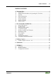
• Feldbus Coupler 750-344 / -345 Hardware 3.1.2 Hardware 3.1.2.1 View INTERBUS READY 750-344 Fieldbus connection D-Sub incoming BA RC Status indication -Fieldbus -Fieldbus node Data contacts RD I/O 01 02 03 04 Fieldbus connection D-Sub outgoing Supply 24V 0V Marking area Configuration interface Fig.
Feldbus Coupler 750-344 / -345 Hardware • 49 3.1.2.2 Power Supply Fieldbus Interface The power is supplied via terminals with CAGE CLAMP® connection. The power supply powers the system. I/O Modules 1/2 24 V 24 V 5V 10 nF Electronic 5V 0V 15 nF 1M Fieldbus Interface Electronic 3/4 Fieldbus Interface Fieldbus Interface 10 nF 0V 24 V 1 2 3 4 750-344 Fig. 3-2: Power supply g034401e The integrated power supply provides the required power to the electronics and I/O modules.
• Feldbus Coupler 750-344 / -345 Hardware 3.1.2.3 Fieldbus Connection The WAGO-I/O SYSTEM 750 for INTERBUS is equipped with two 9-pole D-SUB connectors for fieldbus connection. INTERBUS makes a distinction between the "incoming" and "outgoing" interface. Input interface: 9 pole D-Sub (male) DO1 DI1 GND1 GND1 VCC1 Fig. 3-3: 1 2 3 4 5 6 7 8 9 DO1 DI1 VCC1 n.c. "Connector" terminal assignment g012231e The incoming interface provides electrical isolation between the fieldbus and the bus coupler.
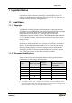
Feldbus Coupler 750-344 / -345 Hardware • 51 3.1.2.4 Indicators The operating status of the fieldbus couplers and of the node is signaled via light diodes (LEDs). Fig. 3-5: Indicators 750-344 g012232x LED Color Meaning READY green The READY LED shows the status for power supply and the operational readiness of the coupler. BA green The BA LED shows that the bus is active, with data transfer taking place. RC green The RC LED shows the status of the incoming interface.
• Feldbus Coupler 750-344 / -345 Operating system 3.1.3 Operating system The system can be started up after configuring the INTERBUS Master system and after electrical installation of the fieldbus station. The coupler checks the data bus when power is applied. Following this the I/O modules and the present configuration is determined. At the same time, a list is generated which is not visible from outside.
Feldbus Coupler 750-344 / -345 Process Image • 53 3.1.4 Process Image 3.1.4.1 Local Process Image After being switched on, the coupler identifies all I/O modules connected that supply or are expected to receive process data (data width or bit width > 0). In nodes analog and digital I/O modules can be fitted mixed. NOTE: For the number of input and output bits and bytes of the individual connected I/O modules, please see the corresponding descriptions of the I/O modules.
• Feldbus Coupler 750-344 / -345 Process Image Based on this break-down, the first addresses assigned in the configuration are reserved for analog inputs and outputs. Counting is from left to right, beginning with the first analog channel next to the bus coupler. 3.1.4.3 Bus Modules Process Images on the Interbus The status bytes (S), control bytes (C) and data bytes (D0...Dn) for for byteand word-oriented modules are mapped in the Motorola format on the Interbus.
Feldbus Coupler 750-344 / -345 Process Image • 55 3.1.4.3.3 4 DI Modules 750-402, 750-403, 750-408, 750-409, 750-414, 750-415, 750-422,750-423, 750-424 Process Image in [Bit] INTERBUS Input Output 4 0 Input Output 8 0 3.1.4.3.4 8 DI Modules 750-430, 750-431 Process Image in [Bit] INTERBUS 3.1.4.3.5 2 DO Modules 750-501, 750-502, 750-509, 750-512, 750-513, 750-514, 750-517, 750-535 Process Image in [Bit] INTERBUS Input Output 0 2 3.1.4.3.
• Feldbus Coupler 750-344 / -345 Process Image 3.1.4.3.7 4 DO Modules 750-504, 750-516, 750-519 Process Image in [Bit] INTERBUS Input Output 0 4 Input Output 0 8 Input Output 2 0 3.1.4.3.8 8 DO Modules 750-530 Process Image in [Bit] INTERBUS 3.1.4.3.9 Supply modules 750-610, 750-611 (with diagnostics) Process Image in [Bit] INTERBUS 3.1.4.3.
Feldbus Coupler 750-344 / -345 Process Image 3.1.4.3.11 4 AI Modules 750-453, 750-455, 750-457, 750-459, 750-460, 750-463, 750-468 Process Image in [Byte] INTERBUS Input Output 8 0 INTERBUS Mapping MOTOROLA Channel 1 Channel 2 Channel 3 Channel 4 3.1.4.3.
• Feldbus Coupler 750-344 / -345 Process Image 3.1.4.3.13 4 AO Modules 750-551, 750-553, 750-555, 750-557, 750-559 Process Image in [Byte] INTERBUS Input Output 0 8 INTERBUS Mapping MOTOROLA Channel 1 Channel 2 Channel 3 Channel 4 Input Output - D1 - D0 - D3 - D2 - D5 - D4 - D7 - D6 Input Output 6 6 3.1.4.3.
Feldbus Coupler 750-344 / -345 Process Image 3.1.4.3.15 PWM Modules 750-511 Process Image in [Byte] INTERBUS Input Output 6 6 INTERBUS Mapping MOTOROLA Channel 1 Channel 2 3.1.4.3.
• Feldbus Coupler 750-344 / -345 Process Image 3.1.4.3.17 Incremental Encoder Interface 750-631, 750-634, 750-637 Process Image in [Byte] INTERBUS Input Output 6 6 INTERBUS Mapping MOTOROLA Channel 1 3.1.4.3.
Feldbus Coupler 750-344 / -345 Process Image 3.1.4.3.
• Feldbus Coupler 750-344 / -345 Configuration 3.1.5 Configuration 3.1.5.1 INTERBUS Files Further information INTERBUS files for configuring I/O modules are available under item number 750-913 on disk, or at the WAGO Internet site. http://www.wago.com 3.1.5.2 ID Code During the ID cycle, which is performed for initialization of the INTERBUS system, the connected subscribers (slaves) "declare" themselves by their function and their byte length.
Feldbus Coupler 750-344 / -345 Configuration • 63 3.1.5.3 ID Code to the WAGO I/O System On account of common use of digital, analog and special function at one fieldbus station, the structure of the INTERBUS ID codes makes it necessary to use more than one ID code. The WAGO INTERBUS coupler reports in as a remote bus subscriber with a variable length. The ID code 0x3c is set when power is switched on.
• Feldbus Coupler 750-344 / -345 Configuration 3.1.5.4 Example Allocation can be clearly illustrated here by a fieldbus node with a coupler and 18 I/O modules. Fig. 3-9: Application example No. I/O module g012234x Master addresses *) Inputs Outputs --- 1 Power supply --- 2 Digital input P32.0 Digital input P32.1 Digital input P32.2 Digital input P32.3 Digital input P32.4 Digital input P32.5 Digital input P32.6 Digital input P32.7 Digital input P33.0 Digital input P33.
Feldbus Coupler 750-344 / -345 Configuration No. I/O module Master addresses *) Inputs 9 10 Outputs Digital output P29.0 Digital output P29.1 Digital output P29.2 Digital output P29.3 Digital output P29.4 Digital output P29.5 Digital output P29.6 Digital output P29.
• Feldbus Coupler 750-344 / -345 Diagnostics 3.1.6 Diagnostics 3.1.6.1 Standard Couplers 750-344 and 750-345 The bus coupler reports an error in the periphery to the master when there is a disturbance of data bus operation. The bus coupler cancels the error message when the error has been eliminated. 3.1.6.2 Diagnostics Couplers 750-344/000-003 and 750-345/000-003 In addition to providing periphery error messages (see above), this bus coupler also provides diagnostics information to the process data.
Feldbus Coupler 750-344 / -345 Diagnostics • 67 3.1.6.2.2 Diagnostics Word in the Process Output Image The diagnostics output word (first work in the process output image) has the following functions.
• Feldbus Coupler 750-344 / -345 Diagnostics 3.1.6.2.3 Diagnostics Word in the Process Input Image The diagnostics input word (first work in the process input image) has the following functions. Data bit Meaning for module error Meaning for bus coupler error D15 Type of error for identifying the error source D14 D13 D12 D11 D10 Error code for identifying the type of error Blink code D9 D8 D7 Channel number 0..
Feldbus Coupler 750-344 / -345 Diagnostics • 69 The error codes for module errors are explained in the following table: Error code Meaning 0000B No error 0001B 0010B General error 0011B 0100B 0101B Fuse error (digital module) 0110B 0111B 1000B 1001B No power (digital module) 1010B Wire break (digital module) 1011B 1100B 1101B 1110B 1111B Short circuit (digital module) 3.1.6.2.
• Feldbus Coupler 750-344 / -345 LED Indication 3.1.7 LED Indication For the on-site diagnostics the coupler has five LEDs, which display the operating status of the coupler or the complete node. Fig. 3-10: Indicators 750-344 g012232x 3.1.7.
Feldbus Coupler 750-344 / -345 LED Indication • 71 3.1.7.3 Node Status The I/O-LED indicates the operation of the node and signals faults occurring.
• Feldbus Coupler 750-344 / -345 LED Indication After eliminating the error, restart the coupler by turning the power supply off and on again. 3.1.7.4 Fault Message via Blink Code of the I/O LED Error Argument Error description Solution Error Code 1: Hardware and Configuration Error 1 Compile buffer overflow. Contact the Service office. 2 Unknown data type. Contact the Service office. 3 Checksum error for parameter data Contact the Service office. 4 Error during writing of parameter memory.
Feldbus Coupler 750-344 / -345 LED Indication Error Argument Error description • 73 Solution Error code 4: data error internal data bus 0 n* (n>0) Data error on data bus, data bus disrupted downstream of coupler. Switch off the power for the coupler. Connect the module downcircuit of the coupler, or replace the existing coupler and switch the power back on. Data bus disruption downstream of Switch off the power for the modules. coupler. Replace the nth module and switch power back on.
• Feldbus Coupler 750-344 / -345 Fault behavior 3.1.8 Fault behavior 3.1.8.1 Loss of fieldbus A fieldbus failure is indicated, for example, if the master is switched off or if the bus cable is interrupted. An error at the master can also result in a fieldbus failure. On a failure of the fieldbus, the green BA LED goes out and the coupler deactivates all outputs.
Feldbus Coupler 750-344 / -345 Technical Data 3.1.9 Technical Data System data Number of I/O modules 256 Number of I/O points 4096 (dependent on master) Transmission medium certified CU cable Fieldbus segment length 400 m at 500 Kbit/s (750-344) 150 m at 2 Mbit/s (750-345) Baud rate 500 kBaud (750-344) 2 MBaud (750-345) Data transmission time with 10 slaves, each with 32 DIs and 32 DOs approx. 1.4 ms (750-344) approx. 0.
• I/O Modules 4 I/O Modules This manual does not contain a detailed description of the fieldbus independent WAGO-I/O-SYSTEM 750 I/O modules. Further information Refer to the standard manual or the specific data sheets for information about the I/O modules. Current information about these is also given on the Internet at www.wago.
INTERBUS • 77 5 INTERBUS 5.1 Overview INTERBUS is standardized as a fieldbus in EN 50 254. This bus is set up as a data ring with a central bus master linked to bus slaves. There are several types of INTERBUS variants, with two fieldbus variants listed here for decentralized periphery: Remote bus Installation remote bus 5.1.1 Remote Bus Features 1 Master, up to 256 Slaves Ring structure with active coupling of subscribers Max. length of fieldbus segment 400 m / 150 m Max. expansion 12.
• INTERBUS 5.1.2 Description The physical structure of the bus is set up as a point-to-point link between the subscribers. Each subscriber has an "incoming" bus and an "outgoing" bus. Remote bus Master Remote bus device Remote bus segment Bus coupler Remote bus device Remote bus device Remote bus device Remote bus device Fig.
INTERBUS • 79 The subscribers are assigned their address automatically based on their physical position in the bus system. Control signals (CLOCK, RESET, SELECT, CONTROL) allow each single subscriber to be monitored. Each subscriber has its own ID register that contains information about the type of module, number of I/O addresses and status and error status data. The INTERBUS uses two operating modes: 1.
• INTERBUS 5.2 Interface Modules Master operation is performed by a central control system, such as PLC, NC or RC. The fieldbus devices are linked via interface modules. Interface modules for programmable logic controllers (PLCs) and PC interface cards are available from different manufacturers for INTERBUS. 5.3 Configuration Software The interface modules must be configured with the specific station data to enable links to be set up between the PLC and the fieldbus devices.
INTERBUS WAGO-I/O-SYSTEM 750 INTERBUS • 81