
Operation Manual

16 ProSpray 3.21
GB
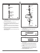
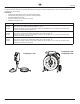
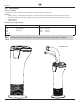
Repairs at the unit
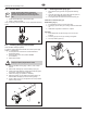
17. Carefullytightenretainernut(5)withadjustingwrench
18. Slidethetopofthepiston(3)intotheT-slot(9)onthe
sliderassembly(4).
19. Positionthepumpmanifold(2)underneaththegearunit
housing and push up until it rests against the gear unit
housing.
20. Attachpumpmanifold(2)tothegearunithousing.
21. Screwpumpmanifold(2)tightlytogearunithousing.
22. LubricateO-ring(Fig.11,Item6)betweenpumpmanifold
(2)andinletvalvehousingwithmachinegrease.Screw
inlet valve housing to the pump manifold.
23. Insert the elbow on the siphon assembly into the bottom
of the pusher stem housing. Push the retaining clip up
into the groove inside the foot valve housing to secure the
siphon assembly in position. Place the return tube over
thereturntubettingandsecurewiththeclip.
24. Install front cover.
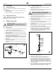
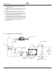
11.4 ProSpray 3.21 connection diagram
Capacitor Assembly
P/N 0522054
Black
White
Blue
Black
P/N 0516360
P/N 0516360
Motor
Red (+)
Black (-)
Red (+)
Black (-)
Potentiometer
Power Cord
EMI Filter
Ground
Ground
PC Board
Assembly
Pressure
Transducer
Black
Red
WhiteGray
Circuit
Breaker
Switch
L.E.D.
BlackBlack