
User manual

GB
10
TurboRoll
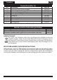
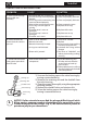
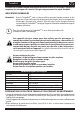
CORRECTION OF MALFUNCTIONS
PROBLEM CAUSE SOLUTION
A. There is paint leakage
on the roller arm
assembly
The seal on the arm is backward.1)
The seal and cap were not properly 2)
cleaned.
The O-ring and the connecting area 3)
were not cleaned properly.
Paint residue on connecting areas4)
The O-rings are damaged or 5)
missing
The roller cover is worn or 6)
damaged
The core or cap is worn or 7)
damaged
The roller arm is worn8)
Turn the seal around1)
Clean and properly lubricate 2)
Clean and properly lubricate 3)
Clean connecting areas4)
Replace the O-rings 5)
Replace roller cover 6)
Replace core or cap 7)
Replace roller arm8)
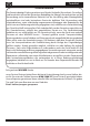
B. Piston rod does not
move when the switch is
pressed
Lever is set to "MANUAL"1)
Batteries too weak2)
Batteries incorrectly inserted 3)
O-rings are not lubricated 4)
Piston rod is jammed5)
Set lever to "POWER"1)
Replace2)
Insert correctly (note marking 3)
in battery compartment)
Lubricate the O-rings on the
4)
plunger
Set lever to "MANUAL" and
5)
release piston rod by pushing/
pressing
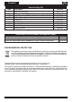
C. The ll tube will not ll
with paint or paint leaks
from ll valve
Paint residue on ll valve 1)
components
Insert ll tube rmly into 1)
ll valve and twist ll tube
several times to break up
paint residue.
If the problem persists, refer to
2)
the steps below to clean the ll
valve components.
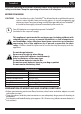
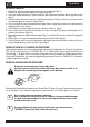
Locking cap
Retaining disk
Duckbill valve
Valve housing
Connecting
area
Unscrew the locking cap on the valve housing by 1)
turning counterclockwise.
Remove the retaining disk and the duckbill from
2)
the valve housing
Clean these parts thoroughly using the appropriate
3)
cleaning solution.
Replace the duckbill valve and retainer disk.4)
Screw the locking cap on the valve housing by 5)
turning it counterclockwise.
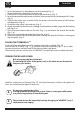
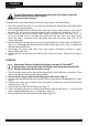
i
NOTICE: If after extended use you nd the plunger dicult to pull while
lling, apply a generous amount of petroleum jelly around the o-rings
located at the end of the plunger (Fig. 2). We have included a packet of
petroleum jelly for you convenience.