
Technical data
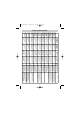
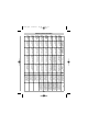
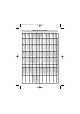

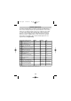

Vehicle-specific information
BMW 3er E36
year of make:
91-
BMW 3er E36
year of make:
91-
BMW 3er E36
year of make:
82-90
Audi A4 Type
B5, year of
make: 94-
without DWA
Audi A4 Type
B5, year of
make: 94-
without DWA
Audi A3 Type
8L, year of
make: 96-01
Audi 100 and
A6 Type C4,
year of make:
90 - 97 with
DWA
Audi 100 and
A6 Type C4,
year of make:
90-97 without
DWA
Audi 80 Type
89 and B4,
year of make:
86-94
blue/green, in the
wiring loom at the
left entry
blue/green, in the
wiring loom at the
left entry
green/blue 30-pole
white plug below the
instrument panel
black/white, in the
wiring loom at the
left entry
black/white, in the
wiring loom at the
left entry
black/white, in the
wiring loom at the
left entry
black/white, in the
wiring loom at the
left entry
black/white, in the
wiring loom at the
left entry
black/white, in the
wiring loom at the
left entry
Left-turn signal,
colour of cable,
position
blue/brown, in the
wiring loom at the
left entry
blue/brown, in the
wiring loom at the
left entry
green/black / 30-pole
white plug below the
instrument panel
black/green, in the
wiring loom at the
left entry
black/green, in the
wiring loom at the
left entry
black/green, in the
wiring loom at the
left entry
black/green, in the
wiring loom at the
left entry
black/green, in the
wiring loom at the
left entry
black/green, in the
wiring loom at the
left entry
Right-turn signal,
colour of cable,
position
Pin 4 / 26 way yellow
connector at the
control unit of the
central locking
Pin 25 / 26 way
white connector at
the control unit of the
central locking
green/blue, central
locking control unit
Pin 6
grey/white, A-pillar
on the left, coming
out of the driver’s
door
green/blue, A-pillar
on the left coming
out of the driver’s
door
grey/black, A-pillar
on the left, coming
out of the driver’s
door
brown/green, A-pillar
on the left coming
out of the driver’s
door
green/blue, A-pillar
on the left, coming
out of the driver’s
door
green/blue A-pillar on
the left
CL to cable colour,
position
Pin 17 / 26 way yel-
low connector at the
control unit of the
central locking
Pin 24, 26-way
white connector of
the central locking of
the control unit
yellow/blue, central
locking control unit
Pin 7
brown/grey, A-pillar
on the left, coming
out of the driver’s
door
green/blue, A-pillar
on the left coming
out of the driver’s
door
brown/red or grey,
A-pillar on the left,
coming out of the
driver’s door
brown/grey, A-pillar
on the left, coming
out of the driver’s
door
green/blue, A-pillar
on the left, coming
out of the driver’s
door
green/blue A-pillar
on the left
CL to colour of
cable, position
No. 3
No. 3
No. 4
No. 4
No. 6
No. 4
No. 4
No. 6
No. 6
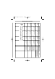
Circuit
dia-
gram
brown/grey /yellow on
the door switch on the
left front at the B-pillar.
The door switch is swi-
tched to negative.
brown/grey/yellow on
the door switch on the
left side at the B-pillar.
The door switch is swi-
tched to negative.
brown/yellow on the
door switch on the left
side at the A-pillar. The
door switch is switched
to negative.
brown/white on the door
switch on the left front
at the A-pillar. The door
switch is switched to
negative.
grey on the door switch
on the left front at the A-
pillar. The door switch is
switched to negative.
brown/white on the door
switch on the left side at
the A-pillar. The door
switch is switched to
negative.
brown/yellow on the
door switch on the left
side at the A-pillar. The
door switch is switched
to negative.
brown/yellow on the
door switch on the left
side at the A-pillar. The
door switch is switched
to negative.
brown/white on the door
switch on the left front
at the A-pillar. The door
switch is switched to
negative.
Door switch, colour of
cable, position
If necessary, contact pins of BMW
with original part number
61130005199 will be needed. The
control unit of the central locking is
behind the glove compartment.
If necessary, contact pins of BMW
with original part number
61130005199 will be needed. The
control unit of the central locking is
behind the glove compartment.
Central locking — control unit is
located on the left side in the A-pil-
lar
blue/yellow control wire to be con-
nected in direction of the door —
grey/red wire direction of the pump
of the central locking.
blue/yellow control wire to be con-
nected in direction of the door —
grey/red wire direction of the pump
of the central locking.
blue/yellow control wire to be con-
nected in direction of the door —
grey/red wire direction of the pump
of the central locking.
Note
52
MS-650.qxd 13/08/03 12:58 Page 52