titelseite_neu_a5.fm Seite 1 Donnerstag, 20.
manual ml-22/44 29.06.2004 8:32 Uhr Seite 2 Inhaltsverzeichnis Hinweise zur Benutzung der Einbauanleitung . . . . . . . . . . . . . . . . . . . . . . . . . . . . . . . . . . . 2 Zubehör. . . . . . . . . . . . . . . . . . . . . . . . . . . . . . . . . . . . . . . . . . . . . . . . . . . . . . . . . . . . . . . . . 2 Sicherheits- und Einbauhinweise . . . . . . . . . . . . . . . . . . . . . . . . . . . . . . . . . . . . . . . . . . . 3-4 Lieferumfang . . . . . . . . . . . . . . . . . . . . . . . . . . . .
manual ml-22/44 29.06.
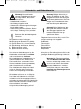
manual ml-22/44 29.06.2004 8:32 Uhr Seite 4 Sicherheits- und Einbauhinweise Diodenprüflampe Achtung! Zum Prüfen der Spannung in elektrischen Leitungen darf nur eine Diodenprüflampe oder ein Voltmeter benutzt werden. Prüflampen mit einem Leuchtkörper nehmen zu hohe Ströme auf und die Fahrzeugelektronik kann beschädigt werden. Prüflampe oder Voltmeter Achtung! Um Schäden zu vermeiden, auf ausreichenden Freiraum für den Bohreraustritt achten. Jede Bohrung entgraten und mit Rostschutzmittel behandeln.
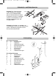
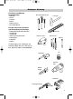
manual ml-22/44 29.06.2004 8:32 Uhr Seite 5 Benötigtes Werkzeug Für Einbau und Montage werden benötigt: - Maßstab - Körner - Hammer - Bohrer - Bohrmaschine - Schraubendreher Schraubendrehersatz Für den elektrischen Anschluss und Überprüfung wird benötigt: - Diodenprüflampe oder Voltmeter - Krimpzange - Isolierband - Wärmeschrumpfschlauch - Heißluftföhn - Lötkolben - Lötzinn Hammer Maßstab Bohrmaschine Bohrersatz Körner Zur Befestigung von Empfänger und Kabel benötigen Sie evtl.
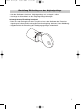
manual ml-22/44 29.06.2004 8:32 Uhr Seite 6 Einbau der Steuereinheiten Mechanischer Einbau Beginnen Sie mit dem Einbau an der Fahrertür. Handkurbel des Fensterhebers und Armlehne abnehmen und die Türinnenverkleidung entfernen. Plastikfolie vorsichtig von unten her lösen. Eine günstige Position für die Steuereinheit (B) in der Nähe der Verriegelungsstange wählen, die den Verriegelungsknopf mit dem Türschloss verbindet.
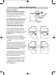
manual ml-22/44 29.06.2004 8:32 Uhr Seite 7 Einstellung ZV-Gestänge an das Originalgestänge - Hub des Stellmotors einfahren, Originalgestänge auf „verriegeln“ stellen. - Gestänge mit Klemmblock an das Originalgestänge befestigen. Achtung! Genaue Einstellung beachten! - Beim Ver- oder Entriegeln mit dem Türschlüssel muss der Stellmotor der Zentralverriegelung auf halbem Schlüsselweg die Zentralverriegelung aktivieren (siehe Abbildung).
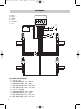
manual ml-22/44 29.06.2004 8:32 Uhr Seite 8 Schaltplan = blau = grün = braun = weiß = schwarz = rot -12 V bl gr br w sc ro Masse GND Anschlüsse Steuerrelais 1 = +12 V – rot 2 = Steuerleitung ZV „zu“ – braun 3 = Motorleitung ZV „auf“ – blau 4 = Ext. Steuerung +12 V = ZV „auf“ 5 = Ext. Steuerung -12 V = ZV „auf“ 6 = -12 V – schwarz 7 = Steuerleitung ZV „auf“ – weiß 8 = Motorleitung ZV „zu“ – grün 9 = Ext. Steuerung +12 V = ZV „zu“ 10 = Ext.
manual ml-22/44 29.06.2004 8:32 Uhr Seite 9 Bohrschablone Bohrung Ø 5 mm Bohrung Ø 5 mm Technische Daten Betriebsspannung Stromaufnahme 12 V ML-22 max. 10 A ML-44 max.
manual ml-22/44 29.06.2004 8:32 Uhr Seite 12 Contents Information for using the installation instructions . . . . . . . . . . . . . . . . . . . . . . . . . . . . . . . .10 Accessories. . . . . . . . . . . . . . . . . . . . . . . . . . . . . . . . . . . . . . . . . . . . . . . . . . . . . . . . . . . . . 10 Safety and installation instructions . . . . . . . . . . . . . . . . . . . . . . . . . . . . . . . . . . . . . . . . . . . 11 Scope of delivery . . . . . . . . . . . . . . . . . . . . . . . . . . . .
manual ml-22/44 29.06.2004 8:32 Uhr Seite 13 Safety and installation instructions - Warning! Improper cable connections may result in short circuits which can cause: cable fires triggering of the airbag damage to electronic control equipment failure of electrical functions (blinkers, brake lights, horn, ignition, lights).
manual ml-22/44 29.06.2004 8:32 Uhr Seite 14 Safety and installation instructions Diode testlamp Caution! To check the voltage in electric cables, use only a diode test lamp or a voltmeter. Test lamps which light up take too much current and the vehicle electronics may be damaged. Testlamp or Voltmeter Caution! To avoid damage, always ensure that there is enough clearance for the drill bit to emerge. Every drill hole must be deburred and treated with a rust proofing agent.
manual ml-22/44 29.06.
manual ml-22/44 29.06.2004 8:32 Uhr Seite 16 Installation of the control unit Mechanical installation Commence installation on the driver’s door. Remove the crank handle of the window winder and the arm rest and remove the inside panelling of the door. Remove the plastic foil carefully from the bottom. Choose a favourable position for the control unit (B) close to the locking rod which connects the locking button to the door lock.
manual ml-22/44 29.06.2004 8:32 Uhr Seite 17 Adjustment central locking rod to original rod - Retract the lifting part of the servomotor, position the original rod to ”lock”. - Fasten the rod to the original rod by means of a clamp. Attention! Pay attention to a precise setting - When the door is locked or unlocked with the door key, the servomotor should actuate the central locking system at half course of the key (see diagram). - Repeat the setting of the connecting rod if necessary.
manual ml-22/44 29.06.
manual ml-22/44 29.06.2004 8:32 Uhr Seite 19 Drill template hole Ø 5 mm hole Ø 5 mm Technical data Operating voltage Input current 12 V ML-22 max. 10 A ML-44 max.
manual ml-22/44 29.06.
manual ml-22/44 29.06.
adresse_A5_05.fm Seite 2 Mittwoch, 21. September 2005 3:46 15 Headquarters WAECO International GmbH · Hollefeldstraße 63 · D-48282 Emsdetten Fon: +49 2572 879-195 · Fax: +49 2572 879-322 · E-Mail: info@waeco.de · Internet: www.waeco.de Europe Overseas + Middle East CH WAECO Schweiz AG Riedackerstrasse 7a CH-8153 Rümlang (Zürich) Fon: +41 44 8187171 Fax: +41 44 8187191 E-Mail: info@waeco.