
Installation & Assembly

2of2
3
4
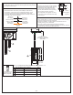
NOTE: ALL DIMENSIONS ARE ROUNDED UP TO THE NEAREST 1/4"
crossbar until the correct length is achieved. Once the Ceiling
Canopy (E) is secure, remove the mounting ball and Ceiling Canopy
(E) and proceed to Step 5.
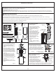
STEP 5 - Wire Connections
A. Use standard wire connectors (not included) to make all wire
connections. (Connectors are not included with fixture.) Twist
connectors until wires are tightly joined together. Wrap each
connection with approved electrical tape and carefully stuff all the
connected wires into the Outlet Box.
White wire
from supply
White wire
from fixture
Black wire from
supply (or Red)
Black wire
from fixture
Ground wire
from supply
Ground wire
from fixture
Figure 5
STEP 6 Install Fixture Body-
A. Carefully tuck all wires into the outlet box
and position the Ceiling Canopy (E) over
the outlet box. Align the holes in the
Ceiling Canopy (E) with the mounting
screws, then attach the Ceiling Canopy
(E) using the previously removed
mounting balls. Hand tighten until snug.
Your fixture is now assembled and ready
to use. Enjoy!
Figure 6
Mounting
Screw
Mounting Ball
A
E
PART NUMBER REPLACEMENT
REQ.
NO.
2
3
GLASS SHADE
1
2
6”L ROD
4
12”L ROD
2
1
G9 CLEAR XENON BULB
1
4.25” Dia.
2.25” Dia.
8”
7”
45.75”
OVERALL HEIGHT
(2) 6” AND (2) 12” RODS
INCLUDED
0.75”
4 75” Dia.
.
1
2
(1) 60W
(Supplied)
Maximum
G9 Xenon Clear
Bulbs
CAUTION FOR BULB REPLACING
A. When replace bulb, turn off power and allow bulb to cool. For safety
purpose, wear gloves and eye protection.
B. If bulb is scratched or cracked, DO NOT use the bulb to avoid
breakage during use or installation.
C. Use only in fixtures rated for lamps wattage and voltage.
D. Lamp operate under high pressure generating intense heat. Prevent
contact with liquid and combustible materials.
FINISH: BRUSHED NICKEL