
Product Manual


LTV Schematics
wc_tx004487en.fm
107
15 Schematics
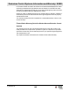
15.1 LTV—Photo Sensor
15.2 Components
12 3 4 56 78 910
11 12 13 14 15 16 17 18 19 20
34
191 BK
192 YL
194 BK
190 RD
193 YL
#1
195 BK
160 RD
1
2
3
4
5
wc_gr015350
Ref. Description Ref. Description
1 Photocell unit 4 Resistor
2 Control module 5 Neutral/ground terminal block
3 Splice — —
Wire Colors
BK Black RD Red YL Yellow OR Orange
GN Green TN Tan BR Brown PU Purple
BU Blue VIO Violet CL Clear SH Shield
PK Pink WH White GY Gray LB Lt. blue