Operator’s Manual Flameless Air Heater HIF 690 EN 5200013292 5 2 0 0 0 02 1 3 0813 2 9 2
Copyright notice © Copyright 2013 by Wacker Neuson Production Americas LLC All rights, including copying and distribution rights, are reserved. This publication may be photocopied by the original purchaser of the machine. Any other type of reproduction is prohibited without express written permission from Wacker Neuson Production Americas LLC. Any type of reproduction or distribution not authorized by Wacker Neuson Production Americas LLC represents an infringement of valid copyrights.
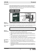
HIF 690 Foreword Foreword SAVE THESE INSTRUCTIONS—This manual contains important instructions for the machine models below. These instructions have been written expressly by Wacker Neuson Production Americas LLC and must be followed during installation, operation, and maintenance of the machines. Machine HIF 690 Item Number 5200012622 wc_gr010995 Machine identification A nameplate listing the model number, item number, revision number, and serial number is attached to this machine.
Foreword HIF 690 The information contained in this manual is based on machines manufactured up until the time of publication. Wacker Neuson reserves the right to change any portion of this information without notice. The illustrations, parts, and procedures in this manual refer to Wacker Neuson factory-installed components. Your machine may vary depending on the requirements of your specific region.
HIF 690 1 Foreword 3 Safety Information 7 1.1 1.2 1.3 1.4 1.5 1.6 1.7 1.8 2 Label Locations .................................................................................. 17 Label Meanings .................................................................................. 18 25 Before Towing Checklist ..................................................................... 25 Tying Down and Transporting the Machine ........................................ 26 Lifting the Machine ...................
Table of Contents 5.2 5.3 5.4 5.5 5.6 5.7 6 46 Machine ...............................................................................................46 Technical Data 7.1 7.2 7.3 8 Machine ...............................................................................................40 Checking the CALFLO™ AF Level ......................................................41 Changing the CALFLO™ AF Filter ......................................................42 Changing the Air Filter Elements ..........
HIF 690 1 1.1 Safety Information Safety Information Signal Words Used in this Manual This manual contains DANGER, WARNING, CAUTION, NOTICE, and NOTE signal words which must be followed to reduce the possibility of personal injury, damage to the equipment, or improper service. This is the safety alert symbol. It is used to alert you to potential personal hazards. f Obey all safety messages that follow this symbol.
Safety Information 1.2 HIF 690 Machine Description and Intended Use The HIF series heaters are flameless air heaters.
HIF 690 1.3 Safety Information Operating Safety DANGER Carbon monoxide. Using the machine indoors CAN KILL YOU IN MINUTES. Exhaust gas contains carbon monoxide (CO). This is a deadly poison you cannot see or smell. If you can smell the exhaust, you are breathing CO. Even if you cannot smell the exhaust, you could be breathing CO. f NEVER operate the machine inside an enclosed area, such as a home, tunnel, or garage. f ONLY use the machine outside and far away from windows, doors, and vents.
Safety Information Application area HIF 690 Be aware of the application area. Keep unauthorized personnel, children, and pets away from the machine. Remain aware of changing positions and the movement of other equipment and personnel in the application area/job site. Be aware of the application area. Do not operate the machine in areas that contain flammable objects, fuels, or products that produce flammable vapors.
HIF 690 1.4 Safety Information Service Safety Service training Before servicing or maintaining the machine: Read and understand the instructions contained in all manuals delivered with the machine. Familiarize yourself with the location and proper use of all controls and safety devices. Only trained personnel shall troubleshoot or repair problems occurring with the machine. Contact Wacker Neuson for additional training if necessary.
Safety Information Personal Protective Equipment (PPE) HIF 690 Wear the following Personal Protective Equipment (PPE) while servicing or maintaining this machine: Close-fitting work clothes that do not hinder movement Safety glasses with side shields Hearing protection Safety-toed footwear In addition, before servicing or maintaining the machine: Tie back long hair. Remove all jewelry (including rings). After Use Stop the engine when the machine is not being operated.
HIF 690 1.5 Safety Information Operator Safety while Using Internal Combustion Engines WARNING Internal combustion engines present special hazards during operation and fueling. Failure to follow the warnings and safety standards could result in severe injury or death. f Read and follow the warning instructions in the engine owner’s manual and the safety guidelines below. DANGER Carbon monoxide. Exhaust gas from the engine contains carbon monoxide, a deadly poison.
Safety Information 1.6 HIF 690 Safety Guidelines for Lifting and Transporting the Machine When lifting the machine: Make sure slings, chains, hooks, ramps, jacks, forklifts, cranes, hoists, and any other type of lifting device used is attached securely and has enough weightbearing capacity to lift or hold the machine safely. See section Technical Data for machine weight. Remain aware of the location of other people when lifting the machine.
HIF 690 1.7 Safety Information Safety Guidelines for Towing the Machine WARNING Risk of severe injury or death. Improper trailer condition and towing technique can lead to an accident. f Obey the trailer manufacturer’s instructions and the instructions below to reduce the risk of an accident. When towing the machine: Do not tow the machine if the towing vehicle’s hitch or the trailer’s coupler are damaged. Do not tow the machine if any of the trailer’s lug nuts are missing.
Safety Information 1.8 HIF 690 Reporting Safety Defects If you believe your trailer has a defect which could cause a crash or could cause injury or death, you should immediately inform the National Highway Traffic Safety Administration (NHTSA) in addition to notifying Wacker Neuson. If NHTSA receives similar complaints, it may open an investigation; and if it finds that a safety defect exists in a group of trailers, it may order a recall and remedy campaign.
HIF 690 2 Labels Labels 2.1 Label Locations n o a w e o n a z n h aa b c x c f b c f x b d n n x g m d e n r t a l n k y p q wc_gr011128 wc_si000773gb.
Labels 2.2 HIF 690 Label Meanings Ref. Label Meaning a DANGER Asphyxiation hazazrd. Heater exhaust contains carbon monoxide. This is a poison you cannot see or smell. Do not operate this machine indoors or in an enclosed area. Read the Operator's Manual. b Tie-down point c Fork lift pocket d Approved stepping location. e WARNING Entanglement hazard. Rotating machinery. Do not reach inside machine when it is running. 18 wc_si000773gb.
HIF 690 Labels Ref. wc_si000773gb.fm Label Meaning f CAUTION Wheel nuts must be tightened to 110 ft.lbs. g WARNING Pressurized contents. Do not open when hot! (Engine radiator) h Weight/mass label. This label indicates the total weight of the machine. k WARNING To reduce the risk of hearing loss, always wear hearing protection when operating this machine. l Use only CALFLO™ AF.
Labels HIF 690 Ref. Label Meaning m WARNING Do not engage trailer jack while transporting the machine. Read the Operator’s Manual for further instructions. n WARNING Hot surface o Lifting point location. Lifting equipment must be rated for 3750 lb (1700 kg). p Ultra low sulfur fuel only 20 wc_si000773gb.
HIF 690 Labels Ref. wc_si000773gb.fm Label Meaning q CAUTION This machine uses diesel fuel. r Block heater location s CALFLO™ AF filter location t Minimum run speed is 1800 RPM. u Use only CALFLO™ AF. v Maximum static pressure 5 inches water column. Maximum air temperature in the duct is 190°F. w Do not use left over gasoline or oil drainings in the machine’s systems. x Drain location for containment skid.
Labels HIF 690 Ref. Label Meaning y y STARTING INSTRUCTIONS 1.Reach inside the heat chamber and on the left rear side of the engine turn the Master Switch clockwise 45 degrees to ON. 2.Depress the fuel pump primer until all air is purged. 3.On the control panel flip the toggle switch to ON position. 4.Hold the Murphy button down. 5.Verify that the "wait to start" red light is OFF before proceeding. 6.Depress the starter button until the engine engages. 7.
HIF 690 Labels Ref. Label Meaning z z TOWING Before towing the Heater, inspect the trailer visually to ensure that the following operations have been completed: 1.Hitch is securely attached to the towing vehicle (safety chain secured). 2.Verify that the fuel tank is completely empty. 3.Taillights are connected and operating. 4.Check for adequate tire pressure. CLEARANCES AND LEVELING Ensure that the heater is level. Maximum "out of level" must not exceed 10 degrees.
Labels HIF 690 Ref. Label Meaning aa aa CAUTION 1.Do not operate the unit in close proximity to combustible surface or materials. 2.Hot while in operation. Do not touch. Keep children, clothing, and combustibles away. 3.Do not refuel while heater is running. 4.Heater must be grounded prior to start up. 5.Do not smoke or use an open flame in heater vicinity while servicing the fuel tank. Failure to comply may result in serious injury or death. 6.Use only approved fuel. 7.
HIF 690 3 3.1 Lifting and Transporting Lifting and Transporting Before Towing Checklist Before towing the machine, check the licensing requirements for trailers in your area. Also check the following items: Towing vehicle Check that the towing vehicle is rated to tow the load. Check that the towing vehicle is in serviceable condition. Do any necessary service/maintenance on the towing vehicle.
Lifting and Transporting 3.2 HIF 690 Tying Down and Transporting the Machine Requirements Procedure Engine shut down Master switch OFF Perform the procedure below to tie down the machine. 1. Make sure that the transport vehicle is capable of handling the weight and size of the machine. See Technical Data for dimensions and operating weight. 2. Close all access doors. a a wc_gr011061 3. Block or chock the wheels and trailer tongue as shown. 4.
HIF 690 3.3 Lifting and Transporting Lifting the Machine Requirements Lifting equipment (crane, hoist, or forklift truck) capable of supporting the machine’s weight Lifting hook and chain capable of supporting the machine’s weight WARNING Crushing hazard. You may be crushed if the lifting devices fail. f Never stand under, or get onto, the machine while it is being lifted or moved. f Use only the designated lifting point to lift the machine.
Lifting and Transporting 3.4 HIF 690 Testing the Breakaway System (Electric Brakes) Requirements Voltmeter Battery charger or backup battery (charged) When Test the breakaway system: Before towing Monthly if the machine is not in service Procedure Perform the following procedure to test the breakaway system. NOTICE: Disconnect the trailer wiring plug from the tow vehicle before testing. Failure to do so will result in severe damage to the electronic brake control. 1.
HIF 690 Lifting and Transporting Continued from the previous page. 5. If the brakes did not function, check the voltage of the breakaway battery. To do so: a. Remove the cover of the battery box. b. Remove the wires connected to the breakaway battery (d). c. Measure the voltage. If 12–14 VDC is not measured, replace or recharge the breakaway battery. d - + F 1000 200 20 V 2 200m A VDC V- COM wc_gr010992 6.
Operation 4 4.1 HIF 690 Operation Control and Component Locations-External b a c d e f o n m k h g wc_gr010989 Ref. Description Ref. Description a Engine exhaust pipe g Fuel tank b Strobe light h Drain fitting c Sky hook k Tie-down d Engine air inlet m Break-away box e Lockable access door n Air inlet and duct adapters f Air outlet and duct adapters o Emergency stop 30 wc_tx003350gb.
HIF 690 4.2 Operation Control and Component Locations-Internal Note: Panels removed for clarity. a b c e d f g n k h m wc_gr010990 Ref. wc_tx003350gb.fm Description Ref.
Operation 4.3 HIF 690 Control and Component Locations-Internal (Continued) Note: Panels removed for clarity. o p q v u r t s x w wc_gr011012 Ref. Description Ref. Description o CALFLO™ AF filter t Battery p CALFLO™ AF reservoir and sightglass u Engine oil filter q Engine alternator v Fuel primer bulb and fuel filter r Coalescent oil filter w Engine oil drain hose s Operator’s Manual holder x CALFLO™ AF drain hose 32 wc_tx003350gb.
HIF 690 4.4 Operation Control Panel Ref 4.5 Description Ref Description a Engine shutoff test handle g Throttle control switch b Fuel gauge h ON/OFF/Glow plug switch c Plate pressure gauge j Start button d Temperature gauge k Murphy switch (engine override) e Thermostat control m Tachometer f Lockable master switch — — Preparing the Machine for First Use 1. Make sure all loose packaging materials have been removed from the machine. 2.
Operation 4.6 HIF 690 Preliminary Checks Requirements Machine on a flat, level surface Before starting Before starting the machine, check the following items: Engine coolant level Engine oil level Engine air filter and housing—replace soiled filters CALFLO™ AF level Diesel fuel level—1/4 tank minimum Condition of intercooler and radiator cooling fins Panels and doors closed Battery charge and terminal connection Air inlet and output areas open and free of obstructions.
HIF 690 4.7 Operation Starting the Engine DANGER Carbon monoxide. Engine exhaust contains carbon monoxide which CAN KILL YOU IN MINUTES. This is a poison that you cannot see or smell. f Do not start the engine in enclosed spaces. NOTICE: The machine will not start if the fuel level is below approximately 10 gallons. Procedure Follow the procedure below to start the engine. 1. Verify that the Master Switch is ON. 2.
Operation HIF 690 Continued from the previous page. Priming the fuel system (if necessary) 7. If the engine does not start, press the primer button (e) on top of the fuel filter (f) several times. Repeat steps 2–6. e f wc_gr011038 Warm-up period 8. Release the Murphy switch (a). a 9. Allow the engine to warm up at 1800 RPM. See topic Preliminary Checks. 10.Adjust the engine rpm, as needed, using the throttle toggle switch (d). Pressing the toggle switch up increases rpm.
HIF 690 4.9 Operation Starting in Cold Weather Background Guidelines In temperatures below freezing, diesel fuel will coagulate and cause problems with starting the machine. The engine will require preheating. Preheating can be achieved using the installed 120V block heater or by using a heater or other heat source indoors. In temperatures between 32°F (0°C) and -20°F (-29°C) the machine should be preheated using the block heater. Plug the block heater into a 120V outlet.
Operation 4.11 HIF 690 Running the Machine DANGER Carbon monoxide. Using the machine indoors CAN KILL YOU IN MINUTES. Exhaust gas contains carbon monoxide (CO). This is a deadly poison you cannot see or smell. If you can smell the exhaust, you are breathing CO. Even if you cannot smell the exhaust, you could be breathing CO. f NEVER operate the machine inside an enclosed area, such as a home, tunnel, or garage. f ONLY use the machine outside and far away from windows, doors, and vents.
HIF 690 Operation Continued from the previous page. Guidelines System efficiency Observe all safety guidelines and instructions in the Operator’s Manual. Do not use engine rpm to adjust output temperature. Keep all doors and panels closed during operation. Use approved Wacker Neuson duct adapters and ducts. Refer to the examples below to determine the settings that will acheive maximum efficiency while running your machine.
Maintenance 5 5.1 HIF 690 Maintenance Maintaining the Emission Control System Normal maintenance, replacement, or repair of emission control devices and systems may be performed by any repair establishment or individual; however, warranty repairs must be performed by a dealer/service center authorized by Wacker Neuson.
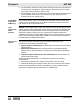
HIF 690 5.3 Maintenance Checking the CALFLO™ AF Level When Daily Requirements Machine off Procedure Perform the procedure below to check the CALFLO™ AF level. 1. Stop the machine. 2. Open the access door. 3. The CALFLO™ AF expands as it heats up. Observe the temperature of the fluid then, observe the sightglass (a). 4. If the CALFLO™ AF level is low, add as necessary. Note: Graphic is representational only. Your machine may vary.
Maintenance 5.4 HIF 690 Changing the CALFLO™ AF Filter When Every 1000 hours Requirements Procedure Engine is stopped and cool to the touch Plastic sheet and container New filter Fresh CALFLO™ AF Follow the procedure below to change the CALFLO™ AF filter. 1. Stop the machine. WARNING Burn hazard. CALFLO™ AF is hot and under pressure at operating temperature. f Stop the machine and let it cool before replacing the filter. 2. Open the access door. 3.
HIF 690 5.5 Maintenance Changing the Air Filter Elements When Requirements Procedure Check daily Replace as needed Engine is stopped and cool to the touch New air filter elements Perform the procedure below to change the air filter elements. 1. Stop the machine. 2. Open the access door. 3. Remove the canister cover and pull out the air filter elements (a). The small inner element (b) is nested inside the large outer element. a b wc_gr011020 4.
Maintenance 5.6 HIF 690 Engine The table below lists basic engine maintenance. Tasks designated with check marks may be performed by the operator. Tasks designated with square bullet points require special training and equipment. Refer to the engine manufacturer’s owner’s manual for additional information.
HIF 690 5.7 Maintenance Storing the Machine Introduction Extended storage of equipment requires preventive maintenance. Performing these steps helps to preserve machine components and ensures the machine will be ready for future use. While not all of these steps necessarily apply to this machine, the basic procedures remain the same. When Prepare your machine for extended storage if it will not be operated for 30 days or more.
Troubleshooting 6 6.1 HIF 690 Troubleshooting Machine Problem Cause Remedy Engine will not crank The master switch is not on. Open the main door of the left side of the machine and turn the master switch on. The battery is dead. Charge the battery and clean the terminals. The glow plug switch is not on. Verify the glow plug switch on the control panel is in the ON position. No fuel. Check the fuel level. Chalwyn valve is activated. Wait a few minutes for the valve to reset.
HIF 690 wc_tx003352gb.fm Troubleshooting Problem Cause Remedy Heat plate oil pressure gauge indicates loss of or reduction in pressure. No CALFLO™ AF in the system. Check the reservoir to verify that there is oil in the sightglass. If not, add CALFLO™ AF. See topic Lubrication. The pressure gauge has malfunctioned. Replace the pressure gauge.
Technical Data 7 7.1 HIF 690 Technical Data Machine Machine HIF 690 Operating weight lbs (kg) 3,750 (1,700) Fuel tank capacityh gal (L) 100 (379) Fuel type Gross heat input Diesel BTU/hr (kW) Blower type 7.2 690,000 (202) Axial Blower motor speed rpm Variable Static pressure in.w.c. (Pa) 5 (1245) Voltage VAC/VDC 120 AC/12 Frequency Hz 60 Heat plate fluid capacity gal (L) 3.5 (13.25) Dimensions in. (mm) 80 (2032) 67 (1701) 155 (3137) wc_gr011115 48 wc_td000579gb.
HIF 690 7.3 Technical Data Engine Engine Power Rating wc_td000579gb.fm Net power rating per ISO 3046. Actual power output may vary due to conditions of specific use. Machine HIF 690 Make Cummins Model 4B3.3T Rated power @ rated speed kW (hp) 54.4 (74) @ 2600 rpm Displacement L (in3) 3.
MSDS: CALFLO™ AF MSDS: CALFLO™ AF Material Safety Data Sheet CALFLO TM AF 1. Product and company identification Product name Code Material uses Manufacturer In case of emergency 2. : CALFLO TM AF : CALAF : CALFLO AF is a heat transfer fluid recommended for non-pressurized, liquid-phase, closed heat transfer systems. : Petro-Canada Lubricants Inc.
MSDS: CALFLO™ AF CALFLO TM AF 4. Page Number: 2 First-aid measures Eye contact : Check for and remove any contact lenses. Immediately flush eyes with plenty of water for at least 15 minutes, occasionally lifting the upper and lower eyelids. Get medical attention immediately. Skin contact : In case of contact, immediately flush skin with plenty of water for at least 15 minutes while removing contaminated clothing and shoes. Wash skin thoroughly with soap and water or use recognised skin cleanser.
MSDS: CALFLO™ AF CALFLO TM AF 6. Accidental release measures Large spill 7. Page Number: 3 : Stop leak if without risk. Move containers from spill area. Approach the release from upwind. Prevent entry into sewers, water courses, basements or confined areas. Wash spillages into an effluent treatment plant or proceed as follows. Contain and collect spillage with non-combustible, absorbent material e.g.
MSDS: CALFLO™ AF CALFLO TM AF 8. Page Number: 4 Exposure controls/personal protection Skin : Personal protective equipment for the body should be selected based on the task being performed and the risks involved and should be approved by a specialist before handling this product. Environmental exposure controls : Emissions from ventilation or work process equipment should be checked to ensure they comply with the requirements of environmental protection legislation.
MSDS: CALFLO™ AF CALFLO TM AF Page Number: 5 11 . Toxicological information Sensitiser Conclusion/Summary : Not available. Carcinogenicity Conclusion/Summary : Not available. Classification Product/ingredient name ACGIH Mixture of severely hydrotreated and A4 hydrocracked base oil (petroleum). Mutagenicity Conclusion/Summary Teratogenicity Conclusion/Summary Reproductive toxicity Conclusion/Summary IARC - EPA - NIOSH - NTP - OSHA - : Not available. : Not available. : Not available. 12 .
MSDS: CALFLO™ AF CALFLO TM AF Page Number: 6 15 . Regulatory information United States HCS Classification : Not regulated. Canada WHMIS (Canada) : Not controlled under WHMIS (Canada). This product has been classified in accordance with the hazard criteria of the Controlled Products Regulations and the MSDS contains all the information required by the Controlled Products Regulations. International regulations Canada inventory United States inventory (TSCA 8b) : All components are listed or exempted.
MSDS: CALFLO™ AF CALFLO TM AF Page Number: 7 16 . Other information To the best of our knowledge, the information contained herein is accurate. However, neither the above-named supplier, nor any of its subsidiaries, assumes any liability whatsoever for the accuracy or completeness of the information contained herein. Final determination of suitability of any material is the sole responsibility of the user. All materials may present unknown hazards and should be used with caution.
Tire Safety Information Tire Safety Information Introduction to Tire Safety Information Federal Regulation 49 CFR 575 requires trailer manufacturers to include certain tire information in the Owner’s Manuals for the trailers they manufacture. This regulation requires that the information be in the English language. This chapter includes all the information required by Federal Regulation 49 CFR 575.
Tire Safety Information 1. TIRE SAFETY INFORMATION This portion of the 8VHU¶V 0DQXDO FRQWDLQV WLUH VDIHW\ LQIRUPDWLRQ DV UHTXLUHG E\ &)5 Section 1.1 contains ³6WHSV IRU 'HWHUPLQLQJ &RUUHFW /RDG /LPLW - Trailer´ . Section 1.2 contains ³6WHSV IRU 'HWHUPLQLQJ &RUUHFW /RDG /Lmit ± Tow Vehicle´. Section 1.3 contains a Glossary of Tire Terminology LQFOXGLQJ ³FROG LQIODWLRQ SUHVVXUH´ ³PD[LPXP LQIODWLRQ SUHVVXUH´ ³UHFRPPHQGHG LQIODWLRQ SUHVVXUH´ DQG RWKHU QRQ-technical terms. Section 1.
Tire Safety Information Excessive loads and/or underinflation cause tire overloading and, as a result, abnormal tire flexing occurs. This situation can generate an excessive amount of heat within the tire. Excessive heat may lead to tire failure. It is the air pressure that enables a tire to support the load, so proper inflation is critical. The proper air pressure may be found on the certification/VIN label and/or on the Tire Placard.
Tire Safety Information Bead The part of the tire that is made of steel wires, wrapped or reinforced by ply cords and that is shaped to fit the rim. Bead separation This is the breakdown of the bond between components in the bead. Bias ply tire A pneumatic tire in which the ply cords that extend to the beads are laid at alternate angles substantially less than 90 degrees to the centerline of the tread. Carcass The tire structure, except tread and sidewall rubber which, when inflated, bears the load.
Tire Safety Information Intended outboard sidewall The sidewall that contains a white-wall, bears white lettering or bears manufacturer, brand, and/or model name molding that is higher or deeper than the same molding on the other sidewall of the tire or the outward facing sidewall of an asymmetrical tire that has a particular side that must always face outward when mounted on a vehicle.
Tire Safety Information Ply A layer of rubber-coated parallel cords. Ply separation A parting of rubber compound between adjacent plies. Pneumatic tire A mechanical device made of rubber, chemicals, fabric and steel or other materials, that, when mounted on an automotive wheel, provides the traction and contains the gas or fluid that sustains the load. Production options weight The combined weight of those installed regular production options weighing over 2.3 kilograms (5 lbs.
Tire Safety Information Tread rib A tread section running circumferentially around a tire. Tread separation Pulling away of the tread from the tire carcass. Treadwear indicators (TWI) The projections within the principal grooves designed to give a visual indication of the degrees of wear of the tread. Vehicle capacity weight The rated cargo aQG OXJJDJH ORDG SOXV NLORJUDPV OEV WLPHV WKH YHKLFOH¶V GHVLJQDWHG VHDWLQJ FDSDFLW\ Vehicle maximum load on the tire The load on an individual tire that is de
Tire Safety Information y p Use this information to make tire safety a regular part of your vehicle maintenance routine. Recognize that the time you spend is minimal compared with the inconvenience and safety consequences of a flat tire or other tire failure. 1.5. SAFETY FIRST±BASIC TIRE M AINTENANCE Properly maintained tires improve the steering, stopping, traction, and load-carrying capability of your vehicle. Underinflated tires and overloaded vehicles are a major cause of tire failure.
Tire Safety Information 1.5.4. STEPS FOR MAINTAINING PROPER TIRE PRESSURE Step 1: Locate the recommended tire pressure on the vehicle's tire information placard, certification label, or in the owner's manual. Step 2: Record the tire pressure of all tires. Step 3: If the tire pressure is too high in any of the tires, slowly release air by gently pressing on the tire valve stem with the edge of your tire gauge until you get to the correct pressure.
Tire Safety Information 1.5.9.1. Information on Passenger Vehicle Tires Please refer to the diagram below. P The "P" indicates the tire is for passenger vehicles. Next number This three-digit number gives the width in millimeters of the tire from sidewall edge to sidewall edge. In general, the larger the number, the wider the tire. Next number This two-digit number, known as the aspect ratio, gives the tire's ratio of height to width.
Tire Safety Information Letter Rating Q R S T U H V W Y Speed Rating 99 mph 106 mph 112 mph 118 mph 124 mph 130 mph 149 mph 168* mph 186* mph * For tires with a maximum speed capability over 149 mph, tire manufacturers sometimes use the letters ZR. For those with a maximum speed capability over 186 mph, tire manufacturers always use the letters ZR. U.S. DOT Tire Identification Number This begins with the letters "DOT" and indicates that the tire meets all federal standards.
Tire Safety Information g Please refer to the following diagram. Tires for light trucks have other markings besides those found on the sidewalls of passenger tires. LT The "LT" indicates the tire is for light trucks or trailers. ST An "ST" is an indication the tire is for trailer use only. Max.
HIF 690 8 Schematics Schematics Page 1 wc_tx003353gb.
Schematics HIF 690 Page 2 wc_gr011129 70 wc_tx003353gb.
Wacker Neuson Produktion GmbH & Co. KG, Preußenstraße 41, D-80809 München, Tel.: +49-(0)89-3 54 02-0 Fax: +49 - (0)89-3 54 02-390 Wacker Neuson Production Americas LLC, N92W15000 Anthony Ave., Menomonee Falls, WI 53051 Tel. : (262) 255-0500 Fax: (262) 255-0550 Tel.: (800) 770-0957 Wacker Neuson Limited - Room 1701–03 & 1717–20, 17/F. Tower 1, Grand Century Place, 193 Prince Edward Road West, Mongkok, Kowloon, Hongkong.