
Operator`s manual

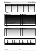


Table Of Contents
- 1 Foreword
- 2. Safety Information
- 2.1 Operating Safety
- 2.2 Service Safety
- 2.3 Operator Safety while using Internal Combustion Engines
- 2.4 Towing Safety
- 2.5 Reporting Trailer Safety Defects
- 2.6 Label Location
- 2.7 Safety and Operating Labels
- 3. Operation
- 3.1 Control Panels
- 3.2 Generator Monitoring
- 3.3 Engine Monitoring
- 3.4 Engine Shutdown Faults
- 3.5 Current Overload Fault
- 3.6 Application
- 3.7 Voltage Selector Switch
- 3.8 Emergency Stop Switch
- 3.9 Main Line Circuit Breaker
- 3.10 Engine Start Switch
- 3.11 Voltage Adjustment Rheostat
- 3.12 Warning Light
- 3.13 Connection Lugs
- 3.14 Ground Connection
- 3.15 Convenience Receptacles
- 3.16 Remote Run Terminal Block
- 3.17 Panel Door Interlock Switch
- 3.18 Terminal Connections
- 3.19 Before Starting
- 3.20 Manual Start-up
- 3.21 Running the Generator
- 3.22 Engine Power Correction Factors
- 3.23 Shutting Down Generator
- 3.24 Cold Weather Start-up
- 3.25 Lifting
- 3.26 Overnight Storage
- 3.27 Long-term Storage
- 3.28 Automatic/Remote Start-up
- 3.29 Remote/Transfer Switch
- 3.30 Towing
- 4. Maintenance
- 4.1 Periodic Maintenance Schedule
- 4.2 New Machines
- 4.3 Resetting the Periodic Maintenance Timer
- 4.4 Air Cleaner
- 4.5 Engine Lubrication
- 4.6 Engine Coolant
- 4.7 Trailer Maintenance
- 4.8 Troubleshooting Automatic Shutdown
- 4.9 Wire Colors
- 4.10 Generator and Receptacle Wiring
- 4.11 Trailer Wiring
- 4.12 G 50/G 70 Engine Wiring
- 4.13 G 85 & G 70 w/ECU Engine Wiring
- 5 Factory-Installed Options
- 5.1 Block Heater
- 5.2 Fuel/Water Separator
- 5.3 Electronic Governor
- 5.4 LCD Strip Heater
- 5.5 Low Coolant Shutdown
- 5.6 Lube Level Maintainer
- 5.7 Temperature-Activated Shutters
- 5.8 Lockable Battery Disconnect
- 5.9 Wiring Diagram
- 5.10 Wiring Diagram Components
- 5.11 Cam-Lock
- 5.12 Containment System
- 6. Technical Data
- 6.1 Engine Data
- 6.2 Generator Data
- 6.3 Trailer and Skid Data
- 6.4 Dimensions
Factory-Installed Options Mobile Generators
wc_tx000380gb.fm 80
5.7 Temperature-Activated Shutters
See Graphic: wc_gr001706, wc_gr001707
The shutters (a) are mounted to the top of the generator enclosure.
The shutters are designed to keep the engine compartment warm, thus
increasing engine temperature during cold weather operation. The
shutters are activated through a wax-pellet actuator (b) that is
connected to the generator's cooling system. As radiator coolant
warms, the wax-pellet actuator engages a linkage (c) that opens the
shutters. As the coolant cools, the shutters close.
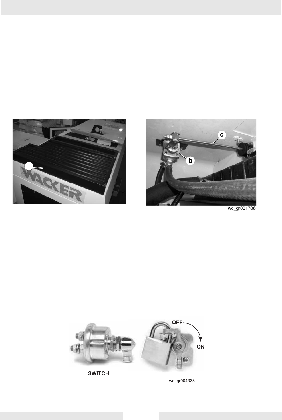
5.8 Lockable Battery Disconnect
See Graphic: wc_gr004338
A lockable ON/OFF switch is available which disconnects the battery.
A padlock (not included) securely locks the switch in the OFF position.
If equipped, the battery disconnect switch is mounted to the upper skid
beneath the access door on either the right or left side of the machine.
NOTICE: Do not use the battery disconnect switch while the engine is
running. Damage to electrical components may occur.
wc_gr001707
a