
Operator`s manual

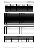


Table Of Contents
- 1 Foreword
- 2. Safety Information
- 2.1 Operating Safety
- 2.2 Service Safety
- 2.3 Operator Safety while using Internal Combustion Engines
- 2.4 Towing Safety
- 2.5 Reporting Trailer Safety Defects
- 2.6 Label Location
- 2.7 Safety and Operating Labels
- 3. Operation
- 3.1 Control Panels
- 3.2 Generator Monitoring
- 3.3 Engine Monitoring
- 3.4 Engine Shutdown Faults
- 3.5 Current Overload Fault
- 3.6 Application
- 3.7 Voltage Selector Switch
- 3.8 Emergency Stop Switch
- 3.9 Main Line Circuit Breaker
- 3.10 Engine Start Switch
- 3.11 Voltage Adjustment Rheostat
- 3.12 Warning Light
- 3.13 Connection Lugs
- 3.14 Ground Connection
- 3.15 Convenience Receptacles
- 3.16 Remote Run Terminal Block
- 3.17 Panel Door Interlock Switch
- 3.18 Terminal Connections
- 3.19 Before Starting
- 3.20 Manual Start-up
- 3.21 Running the Generator
- 3.22 Engine Power Correction Factors
- 3.23 Shutting Down Generator
- 3.24 Cold Weather Start-up
- 3.25 Lifting
- 3.26 Overnight Storage
- 3.27 Long-term Storage
- 3.28 Automatic/Remote Start-up
- 3.29 Remote/Transfer Switch
- 3.30 Towing
- 4. Maintenance
- 4.1 Periodic Maintenance Schedule
- 4.2 New Machines
- 4.3 Resetting the Periodic Maintenance Timer
- 4.4 Air Cleaner
- 4.5 Engine Lubrication
- 4.6 Engine Coolant
- 4.7 Trailer Maintenance
- 4.8 Troubleshooting Automatic Shutdown
- 4.9 Wire Colors
- 4.10 Generator and Receptacle Wiring
- 4.11 Trailer Wiring
- 4.12 G 50/G 70 Engine Wiring
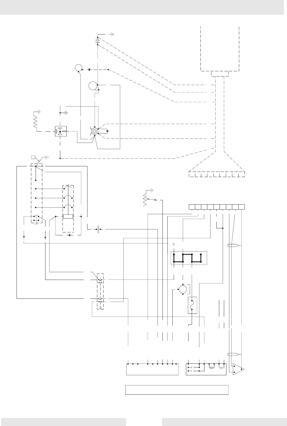
- 4.13 G 85 & G 70 w/ECU Engine Wiring
- 5 Factory-Installed Options
- 5.1 Block Heater
- 5.2 Fuel/Water Separator
- 5.3 Electronic Governor
- 5.4 LCD Strip Heater
- 5.5 Low Coolant Shutdown
- 5.6 Lube Level Maintainer
- 5.7 Temperature-Activated Shutters
- 5.8 Lockable Battery Disconnect
- 5.9 Wiring Diagram
- 5.10 Wiring Diagram Components
- 5.11 Cam-Lock
- 5.12 Containment System
- 6. Technical Data
- 6.1 Engine Data
- 6.2 Generator Data
- 6.3 Trailer and Skid Data
- 6.4 Dimensions
G 50/G 70/G 85 Maintenance
wc_tx000484gb.fm 71
G 85 & G 70 w/ECU Engine Wiring
14
14
B
B
B
-
+
R
R
OR
OR
OR
OR
B+
B+
D+
D+
B+
B+
N2
N2
12
12
R
11
11
86
86
85
85
30
30
B
13
13
GR
GR
65
65
L0
L0
46
46
L1
L1
L2
L2
L2
L2
L3
L3
47
47
79
79
B
Y
C+
C+
B+
B+
50
50
47
47
R
B
R
R
JOHN DEERE
JOHN DEERE
ENGINE ECU
ENGINE ECU
B
W
JD429
JD429
R
62
62
B
+
+
B
-
CRANK DELAY
CRANK DELAY
B SWITCHED
B SWITCHED
START RELAY
START RELAY
21 POSITION
21 POSITION
CONNECTOR
CONNECTOR
A
E
B
G
J
D
V
U
F
A
E
B
G
J
D
V
U
F
ALT / CHARGE
ALT / CHARGE
DASHED LINES ARE PART OF
DASHED LINES ARE PART OF
JOHN DEERE ENGINE HARNESS
JOHN DEERE ENGINE HARNESS
OR
OR
2
OR
OR
45
45
Y
44
44
Y
79
79
LL
LL
60
60
44
44
45
45
Y
OR
OR
20
20
G
NO
NO
46
46
G/Y
G/Y
V
61
61
34
34
G
NO
NO
R
NC
NC
64
64
R
NC
NC
W
B
61
61
10
10
2
1
2
Y
OR
OR
R
51
51
R
20
20
53
53
R
48
48
52
52
52
52
R
49
49
49
49
B+
B+
-
+
+
60
60
62
62
12
12
9
5
53
53
59
59
7
8
6
18
18
5
63
63
1
64
64
4
3
2
BATTERY
BATTERY
Y
G
SH
SH
73
73
75
75
8
7
C
BA
CAN
CAN
J1939
J1939
CRANK
CRANK
RUN/FUEL
RUN/FUEL
REMOTE ANNUNCIATOR
REMOTE ANNUNCIATOR
REMOTE ANNUNCIATOR
REMOTE ANNUNCIATOR
10 A FUSE
10 A FUSE
E-STOP
E-STOP
COLD CRANK
COLD CRANK
DELAY
DELAY
REMOTE START
REMOTE START
FUEL LEVEL
FUEL LEVEL
BATTERY
BATTERY
BATTERY
BATTERY
56
56
3
W
15
15
34
34
56
56
59
59
51
51
HI
HI
63
63
LO
LO
R
R
GR
GR
W / L
W / L
OR
OR
W / V
W / V
B
R
R
Y
V
T
T
wc_gr004614
wc_gr004614
1
2
10
11
16
9
8
3
5
7
12
6
15
13
19
4
17
18
14