
Operator`s manual
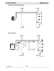


Table Of Contents
- 1 Foreword
- 2. Safety Information
- 2.1 Operating Safety
- 2.2 Service Safety
- 2.3 Operator Safety while using Internal Combustion Engines
- 2.4 Towing Safety
- 2.5 Reporting Trailer Safety Defects
- 2.6 Label Location
- 2.7 Safety and Operating Labels
- 3. Operation
- 3.1 Control Panels
- 3.2 Generator Monitoring
- 3.3 Engine Monitoring
- 3.4 Engine Shutdown Faults
- 3.5 Current Overload Fault
- 3.6 Application
- 3.7 Voltage Selector Switch
- 3.8 Emergency Stop Switch
- 3.9 Main Line Circuit Breaker
- 3.10 Engine Start Switch
- 3.11 Voltage Adjustment Rheostat
- 3.12 Warning Light
- 3.13 Connection Lugs
- 3.14 Ground Connection
- 3.15 Convenience Receptacles
- 3.16 Remote Run Terminal Block
- 3.17 Panel Door Interlock Switch
- 3.18 Terminal Connections
- 3.19 Before Starting
- 3.20 Manual Start-up
- 3.21 Running the Generator
- 3.22 Engine Power Correction Factors
- 3.23 Shutting Down Generator
- 3.24 Cold Weather Start-up
- 3.25 Lifting
- 3.26 Overnight Storage
- 3.27 Long-term Storage
- 3.28 Automatic/Remote Start-up
- 3.29 Remote/Transfer Switch
- 3.30 Towing
- 4. Maintenance
- 4.1 Periodic Maintenance Schedule
- 4.2 New Machines
- 4.3 Resetting the Periodic Maintenance Timer
- 4.4 Air Cleaner
- 4.5 Engine Lubrication
- 4.6 Engine Coolant
- 4.7 Trailer Maintenance
- 4.8 Troubleshooting Automatic Shutdown
- 4.9 Wire Colors
- 4.10 Generator and Receptacle Wiring
- 4.11 Trailer Wiring
- 4.12 G 50/G 70 Engine Wiring
- 4.13 G 85 & G 70 w/ECU Engine Wiring
- 5 Factory-Installed Options
- 5.1 Block Heater
- 5.2 Fuel/Water Separator
- 5.3 Electronic Governor
- 5.4 LCD Strip Heater
- 5.5 Low Coolant Shutdown
- 5.6 Lube Level Maintainer
- 5.7 Temperature-Activated Shutters
- 5.8 Lockable Battery Disconnect
- 5.9 Wiring Diagram
- 5.10 Wiring Diagram Components
- 5.11 Cam-Lock
- 5.12 Containment System
- 6. Technical Data
- 6.1 Engine Data
- 6.2 Generator Data
- 6.3 Trailer and Skid Data
- 6.4 Dimensions
Maintenance G 50/G 70/G 85
wc_tx000484gb.fm 70
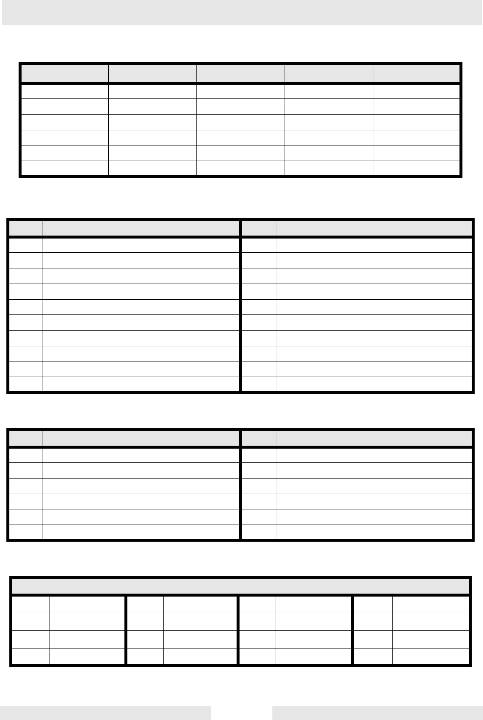
4.13 G 85 & G 70 w/ECU Engine Wiring
Engine
Wires
BOM Revision See Graphic: Revision See Graphic:
0009369 124 & higher wc_gr004614 123 & lower wc_gr002616
0009459 133 & higher wc_gr004614 132 & lower wc_gr002616
0620003 129 & higher wc_gr004614 128 & lower wc_gr002616
0620350 wc_gr004614
0620351 wc_gr004614
0620352 wc_gr004614
Ref. Description Ref. Description
1 Safety interlock switch 11 Intake heater relay
2 Mechanical lugs 12 Plug 2 - engine start outputs
3 Main circuit breaker 13 Run/off/auto switch
4 Shunt 14 Battery
5 Emergency Stop switch 15 10A fuse
6 Engine control module 16 Starter relay
7 Plug 1 - engine sender inputs 17 Starter
8 Remote start contacts 18 Alternator
9 Fuel level sender 19 Terminal block
10 Intake heater
Ref. Description Ref. Description
18 Battery + 62 Fuel Level
53 Battery + 63 Crank
56 Cold Crank Delay 64 Run/Fuel
59 Battery - 73 Remote Annunciator
60 Remote Start 75 Remote Annunciator
61 E-Stop
Wire Colors
B Black R Red Y Yellow Or Orange
G Green T Tan Br Brown Pr Purple
L Blue V Violet Cl Clear Sh Shield
P Pink W White Gr Gray LL Light blue