
Operator`s manual

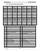

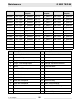


Table Of Contents
- 1 Foreword
- 2. Safety Information
- 2.1 Operating Safety
- 2.2 Service Safety
- 2.3 Operator Safety while using Internal Combustion Engines
- 2.4 Towing Safety
- 2.5 Reporting Trailer Safety Defects
- 2.6 Label Location
- 2.7 Safety and Operating Labels
- 3. Operation
- 3.1 Control Panels
- 3.2 Generator Monitoring
- 3.3 Engine Monitoring
- 3.4 Engine Shutdown Faults
- 3.5 Current Overload Fault
- 3.6 Application
- 3.7 Voltage Selector Switch
- 3.8 Emergency Stop Switch
- 3.9 Main Line Circuit Breaker
- 3.10 Engine Start Switch
- 3.11 Voltage Adjustment Rheostat
- 3.12 Warning Light
- 3.13 Connection Lugs
- 3.14 Ground Connection
- 3.15 Convenience Receptacles
- 3.16 Remote Run Terminal Block
- 3.17 Panel Door Interlock Switch
- 3.18 Terminal Connections
- 3.19 Before Starting
- 3.20 Manual Start-up
- 3.21 Running the Generator
- 3.22 Engine Power Correction Factors
- 3.23 Shutting Down Generator
- 3.24 Cold Weather Start-up
- 3.25 Lifting
- 3.26 Overnight Storage
- 3.27 Long-term Storage
- 3.28 Automatic/Remote Start-up
- 3.29 Remote/Transfer Switch
- 3.30 Towing
- 4. Maintenance
- 4.1 Periodic Maintenance Schedule
- 4.2 New Machines
- 4.3 Resetting the Periodic Maintenance Timer
- 4.4 Air Cleaner
- 4.5 Engine Lubrication
- 4.6 Engine Coolant
- 4.7 Trailer Maintenance
- 4.8 Troubleshooting Automatic Shutdown
- 4.9 Wire Colors
- 4.10 Generator and Receptacle Wiring
- 4.11 Trailer Wiring
- 4.12 G 50/G 70 Engine Wiring
- 4.13 G 85 & G 70 w/ECU Engine Wiring
- 5 Factory-Installed Options
- 5.1 Block Heater
- 5.2 Fuel/Water Separator
- 5.3 Electronic Governor
- 5.4 LCD Strip Heater
- 5.5 Low Coolant Shutdown
- 5.6 Lube Level Maintainer
- 5.7 Temperature-Activated Shutters
- 5.8 Lockable Battery Disconnect
- 5.9 Wiring Diagram
- 5.10 Wiring Diagram Components
- 5.11 Cam-Lock
- 5.12 Containment System
- 6. Technical Data
- 6.1 Engine Data
- 6.2 Generator Data
- 6.3 Trailer and Skid Data
- 6.4 Dimensions
Maintenance G 50/G 70/G 85
wc_tx000484gb.fm 58
BOM Revision See
Graphic:
Revision See
Graphic:
Revision See
Graphic:
0009366 123 & higher wc_gr004692 106–122 wc_gr003171 105 & lower wc_gr002614
0009367 124 & higher wc_gr004692 106–123 wc_gr003171 105 & lower wc_gr002614
0009369 124 & higher wc_gr004692 106–123 wc_gr003171 105 & lower wc_gr002614
0009467 131 & higher wc_gr004692 107–130 wc_gr003171 106 & lower wc_gr002614
0009468 133 & higher wc_gr004692 107–132 wc_gr003171 106 & lower wc_gr002614
0009459 133 & higher wc_gr004692 107–132 wc_gr003171 106 & lower wc_gr002614
0620001 127 & higher wc_gr004692 106–126 wc_gr003171 105 & lower wc_gr002614
0620002 129 & higher wc_gr004692 106–128 wc_gr003171 105 & lower wc_gr002614
0620003 129 & higher wc_gr004692 107–128 wc_gr003171 106 & lower wc_gr002614
0620350 wc_gr004692
0620351 wc_gr004692
0620352 wc_gr004692
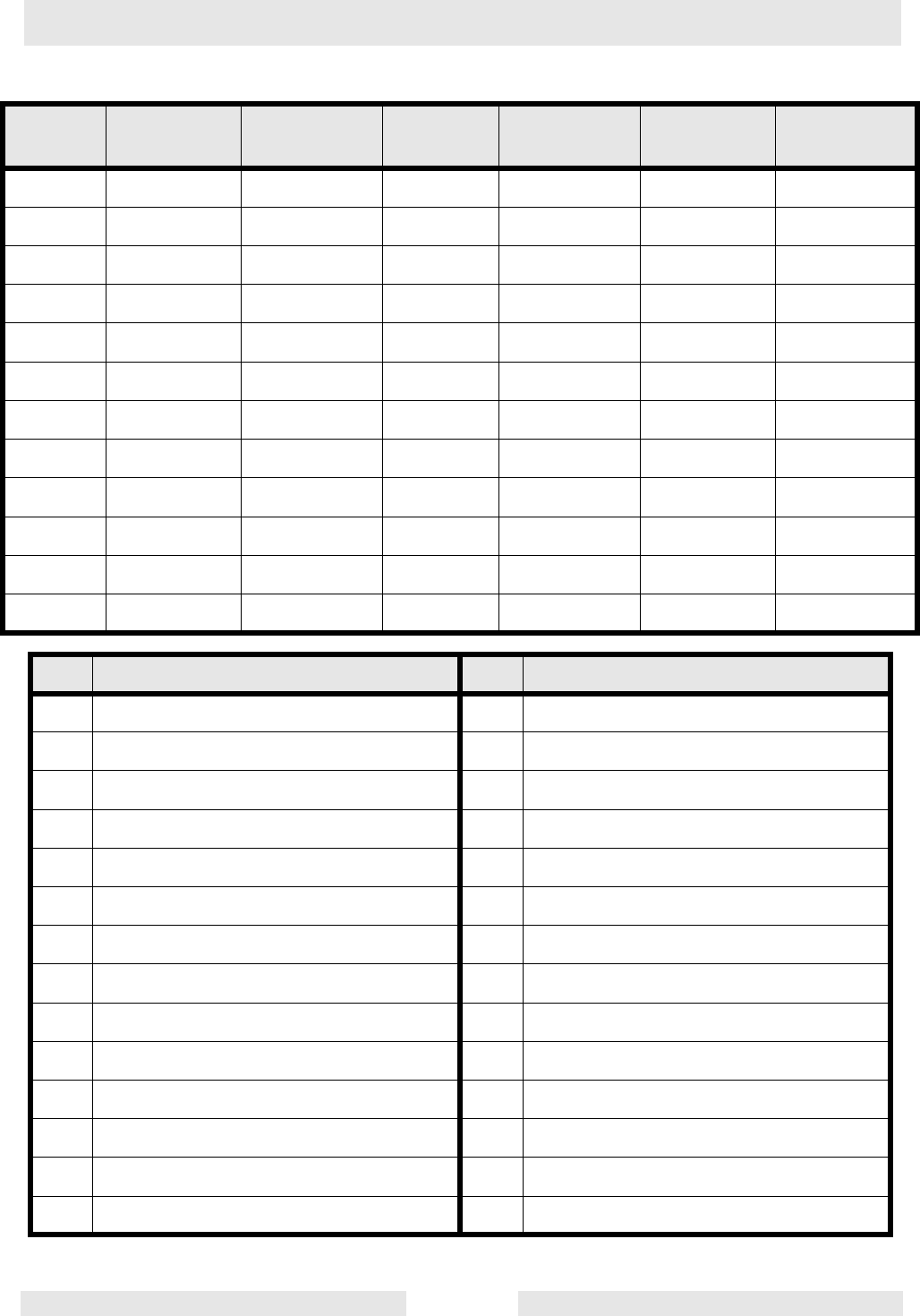
Ref. Description Ref. Description
1 Lug safety limit switch 15 Voltage selector switch
2 Mechanical lugs 16 Generator
3 Plug 3 - current transformer inputs 17 Voltage regulator
4 Plug 4 - line voltage inputs 18 Voltage adjustment rheostat
5 Shunt 19 Terminal Block
6 120V 20A GFI receptacle 20 Exciter
7 120V breaker 21 Stator
8 240V 50A breaker 22 Rotor
9 240V 30A breaker 23 Rectifier
10 240V 50A receptacle 24 Rotor winding
11 240V 30A receptacle 25 Main stator windings
12 Engine control module 26 Auxiliary Stator Winding
13 Main breaker 27 Stator
14 Bond bar 28 Terminal Strip