
Operator`s manual
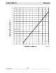


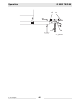
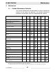

Table Of Contents
- 1 Foreword
- 2. Safety Information
- 2.1 Operating Safety
- 2.2 Service Safety
- 2.3 Operator Safety while using Internal Combustion Engines
- 2.4 Towing Safety
- 2.5 Reporting Trailer Safety Defects
- 2.6 Label Location
- 2.7 Safety and Operating Labels
- 3. Operation
- 3.1 Control Panels
- 3.2 Generator Monitoring
- 3.3 Engine Monitoring
- 3.4 Engine Shutdown Faults
- 3.5 Current Overload Fault
- 3.6 Application
- 3.7 Voltage Selector Switch
- 3.8 Emergency Stop Switch
- 3.9 Main Line Circuit Breaker
- 3.10 Engine Start Switch
- 3.11 Voltage Adjustment Rheostat
- 3.12 Warning Light
- 3.13 Connection Lugs
- 3.14 Ground Connection
- 3.15 Convenience Receptacles
- 3.16 Remote Run Terminal Block
- 3.17 Panel Door Interlock Switch
- 3.18 Terminal Connections
- 3.19 Before Starting
- 3.20 Manual Start-up
- 3.21 Running the Generator
- 3.22 Engine Power Correction Factors
- 3.23 Shutting Down Generator
- 3.24 Cold Weather Start-up
- 3.25 Lifting
- 3.26 Overnight Storage
- 3.27 Long-term Storage
- 3.28 Automatic/Remote Start-up
- 3.29 Remote/Transfer Switch
- 3.30 Towing
- 4. Maintenance
- 4.1 Periodic Maintenance Schedule
- 4.2 New Machines
- 4.3 Resetting the Periodic Maintenance Timer
- 4.4 Air Cleaner
- 4.5 Engine Lubrication
- 4.6 Engine Coolant
- 4.7 Trailer Maintenance
- 4.8 Troubleshooting Automatic Shutdown
- 4.9 Wire Colors
- 4.10 Generator and Receptacle Wiring
- 4.11 Trailer Wiring
- 4.12 G 50/G 70 Engine Wiring
- 4.13 G 85 & G 70 w/ECU Engine Wiring
- 5 Factory-Installed Options
- 5.1 Block Heater
- 5.2 Fuel/Water Separator
- 5.3 Electronic Governor
- 5.4 LCD Strip Heater
- 5.5 Low Coolant Shutdown
- 5.6 Lube Level Maintainer
- 5.7 Temperature-Activated Shutters
- 5.8 Lockable Battery Disconnect
- 5.9 Wiring Diagram
- 5.10 Wiring Diagram Components
- 5.11 Cam-Lock
- 5.12 Containment System
- 6. Technical Data
- 6.1 Engine Data
- 6.2 Generator Data
- 6.3 Trailer and Skid Data
- 6.4 Dimensions
Operation G 50/G 70/G 85
wc_tx000483gb.fm 44
3.29 Remote/Transfer Switch
See Graphic: wc_gr002611
When the generator is used as a standby power supply, it must be
equipped with a device which isolates it from the utility’s distribution
system.
Failure to isolate the generator from the utility’s electrical
distribution system could cause output from the generator to
backfeed into the utility lines and cause injury or death to utility
workers!
The same is true if using the generator as a backup to some other type
of power supply system.
A transfer switch is designed to transfer electrical loads from the
normal power source (utility) to the emergency power source
(generator) when normal voltage falls below a prescribed level.
The transfer switch automatically returns the load back to the normal
source when power is restored back to operating levels.
Installation of a transfer switch or other type of remote starting device
is the responsibility of the generator user. Installation of such devices
must be performed by a qualified electrician following all directions
supplied by the manufacturer of the switch. If attaching generator to a
power supply normally serviced by a utility company, notify the utility
company and check local and state regulations. Familiarize yourself
with all instructions and warning labels supplied with the switch.
The bond bar (t), connecting the neutral and ground lugs, may need to
be removed for standby power applications. Check with NEC and local
regulations for compliance requirements.
When using the generator as a standby or substitute power supply,
make sure the voltage and phase rotation of the line connections
match those of the utility lines, or of any other power source normally
used. Failure to match phase rotation and voltage may cause
equipment connected to the generator to operate incorrectly!
This could create unsafe operating conditions.
Lethal voltage is always present in the transfer switch once it has been
properly installed!
DANGER
WARNING
DANGER