
Operator`s manual


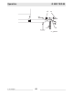
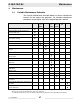
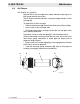

Table Of Contents
- 1 Foreword
- 2. Safety Information
- 2.1 Operating Safety
- 2.2 Service Safety
- 2.3 Operator Safety while using Internal Combustion Engines
- 2.4 Towing Safety
- 2.5 Reporting Trailer Safety Defects
- 2.6 Label Location
- 2.7 Safety and Operating Labels
- 3. Operation
- 3.1 Control Panels
- 3.2 Generator Monitoring
- 3.3 Engine Monitoring
- 3.4 Engine Shutdown Faults
- 3.5 Current Overload Fault
- 3.6 Application
- 3.7 Voltage Selector Switch
- 3.8 Emergency Stop Switch
- 3.9 Main Line Circuit Breaker
- 3.10 Engine Start Switch
- 3.11 Voltage Adjustment Rheostat
- 3.12 Warning Light
- 3.13 Connection Lugs
- 3.14 Ground Connection
- 3.15 Convenience Receptacles
- 3.16 Remote Run Terminal Block
- 3.17 Panel Door Interlock Switch
- 3.18 Terminal Connections
- 3.19 Before Starting
- 3.20 Manual Start-up
- 3.21 Running the Generator
- 3.22 Engine Power Correction Factors
- 3.23 Shutting Down Generator
- 3.24 Cold Weather Start-up
- 3.25 Lifting
- 3.26 Overnight Storage
- 3.27 Long-term Storage
- 3.28 Automatic/Remote Start-up
- 3.29 Remote/Transfer Switch
- 3.30 Towing
- 4. Maintenance
- 4.1 Periodic Maintenance Schedule
- 4.2 New Machines
- 4.3 Resetting the Periodic Maintenance Timer
- 4.4 Air Cleaner
- 4.5 Engine Lubrication
- 4.6 Engine Coolant
- 4.7 Trailer Maintenance
- 4.8 Troubleshooting Automatic Shutdown
- 4.9 Wire Colors
- 4.10 Generator and Receptacle Wiring
- 4.11 Trailer Wiring
- 4.12 G 50/G 70 Engine Wiring
- 4.13 G 85 & G 70 w/ECU Engine Wiring
- 5 Factory-Installed Options
- 5.1 Block Heater
- 5.2 Fuel/Water Separator
- 5.3 Electronic Governor
- 5.4 LCD Strip Heater
- 5.5 Low Coolant Shutdown
- 5.6 Lube Level Maintainer
- 5.7 Temperature-Activated Shutters
- 5.8 Lockable Battery Disconnect
- 5.9 Wiring Diagram
- 5.10 Wiring Diagram Components
- 5.11 Cam-Lock
- 5.12 Containment System
- 6. Technical Data
- 6.1 Engine Data
- 6.2 Generator Data
- 6.3 Trailer and Skid Data
- 6.4 Dimensions

G 50/G 70/G 85 Operation
wc_tx000483gb.fm 43
3.28 Automatic/Remote Start-up
See Graphic: wc_gr002611
In the “REMOTE START” position the generator can be started
remotely, either through a transfer switch or some other type of remote
start switch. “REMOTE START” is the normal setting when using the
generator as a standby power supply. Before placing the generator in
the automatic start-up mode, review the pre-start and manual Start-up
sections in this manual and follow procedure below.
Before placing the Engine Start Switch (f) in the “REMOTE
START” position, verify that the contacts on any remote switch linked
to the generator set are OPEN. This will prevent the generator from
immediately starting when the Engine Start Switch is moved to the
“REMOTE START” position.
3.28.1 Perform a manual start at least once to verify that the metering panel
is operating correctly. Refer to Section Before Starting and Manual
Start-up sections in this manual.
3.28.2 If a check of auto start-up circuit is desired, attach a short jumper wire
(minimum 16 gauge insulated) between the two terminals on the
remote run terminal block. This applies a ground to the Engine Control
Module to complete the start circuit. The engine should crank, start and
run.
Move the Engine Start Switch to off “O” to stop engine. Remove jumper
from remote run terminals after testing is complete.
3.28.3 Secure generator by closing and locking all doors.
3.28.4 Set Engine Start Switch to “REMOTE START” and close main line
circuit breaker.
The generator is now ready for automatic start-up.
If the generator is to be used as a stand-by power supply for more than
a month, provisions must be made to maintain battery charge. This can
be done either by attaching a battery charger to the battery or by
starting generator manually and running engine periodically to
maintain charge. See Section Manual Start-up.
WARNING