
Operator`s manual
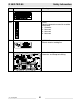
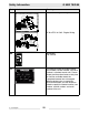
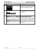

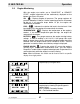
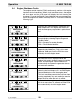
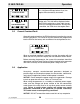

Table Of Contents
- 1 Foreword
- 2. Safety Information
- 2.1 Operating Safety
- 2.2 Service Safety
- 2.3 Operator Safety while using Internal Combustion Engines
- 2.4 Towing Safety
- 2.5 Reporting Trailer Safety Defects
- 2.6 Label Location
- 2.7 Safety and Operating Labels
- 3. Operation
- 3.1 Control Panels
- 3.2 Generator Monitoring
- 3.3 Engine Monitoring
- 3.4 Engine Shutdown Faults
- 3.5 Current Overload Fault
- 3.6 Application
- 3.7 Voltage Selector Switch
- 3.8 Emergency Stop Switch
- 3.9 Main Line Circuit Breaker
- 3.10 Engine Start Switch
- 3.11 Voltage Adjustment Rheostat
- 3.12 Warning Light
- 3.13 Connection Lugs
- 3.14 Ground Connection
- 3.15 Convenience Receptacles
- 3.16 Remote Run Terminal Block
- 3.17 Panel Door Interlock Switch
- 3.18 Terminal Connections
- 3.19 Before Starting
- 3.20 Manual Start-up
- 3.21 Running the Generator
- 3.22 Engine Power Correction Factors
- 3.23 Shutting Down Generator
- 3.24 Cold Weather Start-up
- 3.25 Lifting
- 3.26 Overnight Storage
- 3.27 Long-term Storage
- 3.28 Automatic/Remote Start-up
- 3.29 Remote/Transfer Switch
- 3.30 Towing
- 4. Maintenance
- 4.1 Periodic Maintenance Schedule
- 4.2 New Machines
- 4.3 Resetting the Periodic Maintenance Timer
- 4.4 Air Cleaner
- 4.5 Engine Lubrication
- 4.6 Engine Coolant
- 4.7 Trailer Maintenance
- 4.8 Troubleshooting Automatic Shutdown
- 4.9 Wire Colors
- 4.10 Generator and Receptacle Wiring
- 4.11 Trailer Wiring
- 4.12 G 50/G 70 Engine Wiring
- 4.13 G 85 & G 70 w/ECU Engine Wiring
- 5 Factory-Installed Options
- 5.1 Block Heater
- 5.2 Fuel/Water Separator
- 5.3 Electronic Governor
- 5.4 LCD Strip Heater
- 5.5 Low Coolant Shutdown
- 5.6 Lube Level Maintainer
- 5.7 Temperature-Activated Shutters
- 5.8 Lockable Battery Disconnect
- 5.9 Wiring Diagram
- 5.10 Wiring Diagram Components
- 5.11 Cam-Lock
- 5.12 Containment System
- 6. Technical Data
- 6.1 Engine Data
- 6.2 Generator Data
- 6.3 Trailer and Skid Data
- 6.4 Dimensions
Operation G 50/G 70/G 85
wc_tx000483gb.fm 30
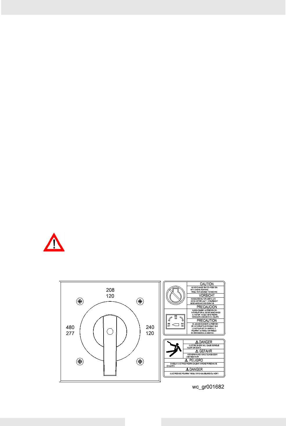
3.7 Voltage Selector Switch
See Graphic: wc_gr001682
The voltage selector switch is located in a separate enclosure on the
generator on the opposite side of the machine.
The selector switch is a three-position switch which mechanically
changes the connections between the generator output leads and the
terminal lugs on the generator. This allows three different volt ranges
to be selected.
120/240 VAC 1Ø
120/208 VAC 3Ø
139/240 VAC 3Ø (Refer to Section Voltage Adjustment Rheostat.)
277/480 VAC 3Ø
Voltage ranges are selected by rotating the handle on the switch to the
desired voltage. The switch is equipped with a locking mechanism.
This allows the voltage setting to be locked in place to prevent
unauthorized personnel from changing the voltage selection. To lock
switch in position, push lock up and attach a padlock through the
openings in the locking strip.
NOTICE: NEVER CHANGE THE VOLTAGE SELECTOR SWITCH
WITH THE ENGINE RUNNING. This can cause arcing and can
severely damage the switch and the generator windings.
DANGER OF ELECTROCUTION! High voltage is present inside this
panel when the generator is operating!
DANGER