
Operator`s manual
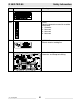
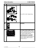
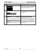

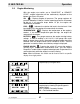
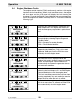
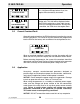

Table Of Contents
- 1 Foreword
- 2. Safety Information
- 2.1 Operating Safety
- 2.2 Service Safety
- 2.3 Operator Safety while using Internal Combustion Engines
- 2.4 Towing Safety
- 2.5 Reporting Trailer Safety Defects
- 2.6 Label Location
- 2.7 Safety and Operating Labels
- 3. Operation
- 3.1 Control Panels
- 3.2 Generator Monitoring
- 3.3 Engine Monitoring
- 3.4 Engine Shutdown Faults
- 3.5 Current Overload Fault
- 3.6 Application
- 3.7 Voltage Selector Switch
- 3.8 Emergency Stop Switch
- 3.9 Main Line Circuit Breaker
- 3.10 Engine Start Switch
- 3.11 Voltage Adjustment Rheostat
- 3.12 Warning Light
- 3.13 Connection Lugs
- 3.14 Ground Connection
- 3.15 Convenience Receptacles
- 3.16 Remote Run Terminal Block
- 3.17 Panel Door Interlock Switch
- 3.18 Terminal Connections
- 3.19 Before Starting
- 3.20 Manual Start-up
- 3.21 Running the Generator
- 3.22 Engine Power Correction Factors
- 3.23 Shutting Down Generator
- 3.24 Cold Weather Start-up
- 3.25 Lifting
- 3.26 Overnight Storage
- 3.27 Long-term Storage
- 3.28 Automatic/Remote Start-up
- 3.29 Remote/Transfer Switch
- 3.30 Towing
- 4. Maintenance
- 4.1 Periodic Maintenance Schedule
- 4.2 New Machines
- 4.3 Resetting the Periodic Maintenance Timer
- 4.4 Air Cleaner
- 4.5 Engine Lubrication
- 4.6 Engine Coolant
- 4.7 Trailer Maintenance
- 4.8 Troubleshooting Automatic Shutdown
- 4.9 Wire Colors
- 4.10 Generator and Receptacle Wiring
- 4.11 Trailer Wiring
- 4.12 G 50/G 70 Engine Wiring
- 4.13 G 85 & G 70 w/ECU Engine Wiring
- 5 Factory-Installed Options
- 5.1 Block Heater
- 5.2 Fuel/Water Separator
- 5.3 Electronic Governor
- 5.4 LCD Strip Heater
- 5.5 Low Coolant Shutdown
- 5.6 Lube Level Maintainer
- 5.7 Temperature-Activated Shutters
- 5.8 Lockable Battery Disconnect
- 5.9 Wiring Diagram
- 5.10 Wiring Diagram Components
- 5.11 Cam-Lock
- 5.12 Containment System
- 6. Technical Data
- 6.1 Engine Data
- 6.2 Generator Data
- 6.3 Trailer and Skid Data
- 6.4 Dimensions

G 50/G 70/G 85 Operation
wc_tx000483gb.fm 29
3.5 Current Overload Fault
Along with engine functions the ECM continuously monitors the current
load in each phase. The values for current overload are programmed
into the ECM at the factory and are different for each generator size.
When an overload condition is sensed in any leg, the engine will shut
down and the LCD panel will display the fault condition shown above.
Before restarting the generator, the cause of the overload should be
determined and eliminated. Review all loads attached to the generator
and make sure they do not exceed the power rating of the unit.
3.6 Application
Heavy-duty, compact, sound-attenuated generators designed to
provide single and three-phase power for construction, commercial,
and industrial applications where reliable power is needed.
NOTICE: Do not exceed the power output of the generator. Damage
to tools or generator will occur. Refer to Technical Data.
When using the generator as a standby or substitute power supply,
make sure the voltage and phase rotation of the line connections
match those of the utility lines or of any other power source normally
used. Failure to match phase rotation and voltage may cause
equipment connected to the generator to operate incorrectly!
This could create unsafe operating conditions.
NOTICE: DO NOT exceed the rated current limit of any receptacle.
Normal operating pressure is between 40–80
psi. If oil pressure drops below 15 psi, the
engine will automatically shut down.
For machines with the Low-Coolant Shutdown
Option only. This fault will be displayed when
the ECM has picked up a signal from the sen-
sor that a low-coolant level exists. During such
a condition, the ECM shuts the engine down.
LOW OIL LEVEL
FAULT
LOW WATER LEVEL
FAULT
OVERLOAD