
Operator`s manual
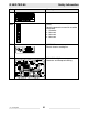
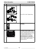
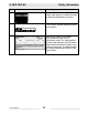

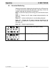
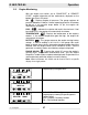
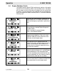
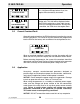

Table Of Contents
- 1 Foreword
- 2. Safety Information
- 2.1 Operating Safety
- 2.2 Service Safety
- 2.3 Operator Safety while using Internal Combustion Engines
- 2.4 Towing Safety
- 2.5 Reporting Trailer Safety Defects
- 2.6 Label Location
- 2.7 Safety and Operating Labels
- 3. Operation
- 3.1 Control Panels
- 3.2 Generator Monitoring
- 3.3 Engine Monitoring
- 3.4 Engine Shutdown Faults
- 3.5 Current Overload Fault
- 3.6 Application
- 3.7 Voltage Selector Switch
- 3.8 Emergency Stop Switch
- 3.9 Main Line Circuit Breaker
- 3.10 Engine Start Switch
- 3.11 Voltage Adjustment Rheostat
- 3.12 Warning Light
- 3.13 Connection Lugs
- 3.14 Ground Connection
- 3.15 Convenience Receptacles
- 3.16 Remote Run Terminal Block
- 3.17 Panel Door Interlock Switch
- 3.18 Terminal Connections
- 3.19 Before Starting
- 3.20 Manual Start-up
- 3.21 Running the Generator
- 3.22 Engine Power Correction Factors
- 3.23 Shutting Down Generator
- 3.24 Cold Weather Start-up
- 3.25 Lifting
- 3.26 Overnight Storage
- 3.27 Long-term Storage
- 3.28 Automatic/Remote Start-up
- 3.29 Remote/Transfer Switch
- 3.30 Towing
- 4. Maintenance
- 4.1 Periodic Maintenance Schedule
- 4.2 New Machines
- 4.3 Resetting the Periodic Maintenance Timer
- 4.4 Air Cleaner
- 4.5 Engine Lubrication
- 4.6 Engine Coolant
- 4.7 Trailer Maintenance
- 4.8 Troubleshooting Automatic Shutdown
- 4.9 Wire Colors
- 4.10 Generator and Receptacle Wiring
- 4.11 Trailer Wiring
- 4.12 G 50/G 70 Engine Wiring
- 4.13 G 85 & G 70 w/ECU Engine Wiring
- 5 Factory-Installed Options
- 5.1 Block Heater
- 5.2 Fuel/Water Separator
- 5.3 Electronic Governor
- 5.4 LCD Strip Heater
- 5.5 Low Coolant Shutdown
- 5.6 Lube Level Maintainer
- 5.7 Temperature-Activated Shutters
- 5.8 Lockable Battery Disconnect
- 5.9 Wiring Diagram
- 5.10 Wiring Diagram Components
- 5.11 Cam-Lock
- 5.12 Containment System
- 6. Technical Data
- 6.1 Engine Data
- 6.2 Generator Data
- 6.3 Trailer and Skid Data
- 6.4 Dimensions
G 50/G 70/G 85 Operation
wc_tx000483gb.fm 27
3.3 Engine Monitoring
With the engine start switch set to “RUN/START” or “REMOTE
START”, engine information will be continuously displayed on the
bottom line of the LCD panel.
OIL - Displays engine oil pressure. The gauge registers oil
pressure between 0–100 psi. Normal operating pressure is between
60–80 psi. If oil pressure drops below 15 psi, the engine will
automatically shut down.
FUEL - Indicates the relative fuel level in the fuel tank. If fuel
level drops to 5% the engine will automatically shut down.
TEMPERATURE - Displays the temperature of the engine's
coolant. If the coolant temperature gets too high, the engine will
automatically shut down.
BATTERY - This gauge measures the engine starting battery
voltage. A normal reading is 13.5–14.5V. If the gauge falls much
below or above these values, the engine charging system should be
checked. With the engine switch set to “REMOTE START” and the
generator in stand-by mode, actual battery voltage is displayed.
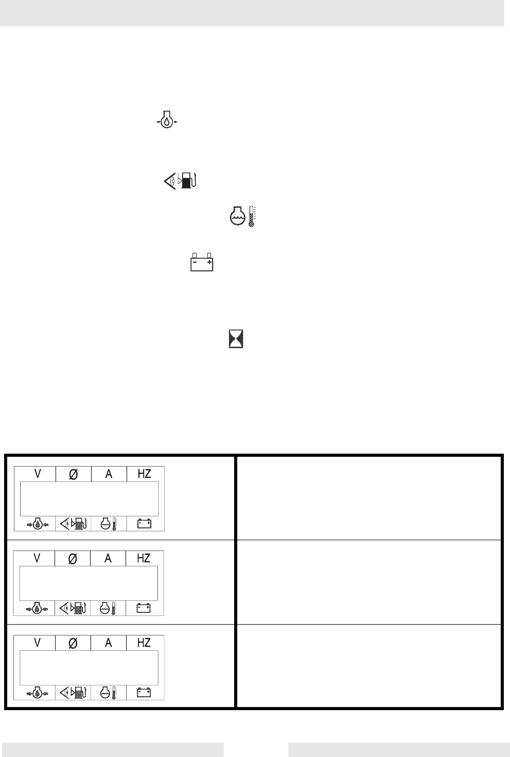
ENGINE HOURS - Pressing the switch UP causes the engine’s
running hours, the periodic maintenance timer, and the Engine
Diagnostic Trouble Codes set points to be displayed. Engine hours are
accumulated only while the engine is actually running.
Note: When held down, this switch can be used to lock in a specific
display for a single phase.
Sample display of engine hours.
Sample display of periodic maintenance timer.
G 85 & G 70 w/ECU only
Sample display showing Engine Diagnostic
Trouble Codes.
SPN = Suspect Parameter Number
FMI = Failure Mode Identifier.
RUNNING HOURS
135.2
TIME TO SERVICE
180.2 hrs.
SPN.FMI 100.01