
Operator`s manual
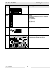
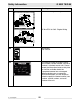
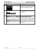

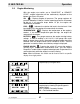
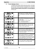
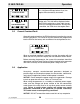

Table Of Contents
- 1 Foreword
- 2. Safety Information
- 2.1 Operating Safety
- 2.2 Service Safety
- 2.3 Operator Safety while using Internal Combustion Engines
- 2.4 Towing Safety
- 2.5 Reporting Trailer Safety Defects
- 2.6 Label Location
- 2.7 Safety and Operating Labels
- 3. Operation
- 3.1 Control Panels
- 3.2 Generator Monitoring
- 3.3 Engine Monitoring
- 3.4 Engine Shutdown Faults
- 3.5 Current Overload Fault
- 3.6 Application
- 3.7 Voltage Selector Switch
- 3.8 Emergency Stop Switch
- 3.9 Main Line Circuit Breaker
- 3.10 Engine Start Switch
- 3.11 Voltage Adjustment Rheostat
- 3.12 Warning Light
- 3.13 Connection Lugs
- 3.14 Ground Connection
- 3.15 Convenience Receptacles
- 3.16 Remote Run Terminal Block
- 3.17 Panel Door Interlock Switch
- 3.18 Terminal Connections
- 3.19 Before Starting
- 3.20 Manual Start-up
- 3.21 Running the Generator
- 3.22 Engine Power Correction Factors
- 3.23 Shutting Down Generator
- 3.24 Cold Weather Start-up
- 3.25 Lifting
- 3.26 Overnight Storage
- 3.27 Long-term Storage
- 3.28 Automatic/Remote Start-up
- 3.29 Remote/Transfer Switch
- 3.30 Towing
- 4. Maintenance
- 4.1 Periodic Maintenance Schedule
- 4.2 New Machines
- 4.3 Resetting the Periodic Maintenance Timer
- 4.4 Air Cleaner
- 4.5 Engine Lubrication
- 4.6 Engine Coolant
- 4.7 Trailer Maintenance
- 4.8 Troubleshooting Automatic Shutdown
- 4.9 Wire Colors
- 4.10 Generator and Receptacle Wiring
- 4.11 Trailer Wiring
- 4.12 G 50/G 70 Engine Wiring
- 4.13 G 85 & G 70 w/ECU Engine Wiring
- 5 Factory-Installed Options
- 5.1 Block Heater
- 5.2 Fuel/Water Separator
- 5.3 Electronic Governor
- 5.4 LCD Strip Heater
- 5.5 Low Coolant Shutdown
- 5.6 Lube Level Maintainer
- 5.7 Temperature-Activated Shutters
- 5.8 Lockable Battery Disconnect
- 5.9 Wiring Diagram
- 5.10 Wiring Diagram Components
- 5.11 Cam-Lock
- 5.12 Containment System
- 6. Technical Data
- 6.1 Engine Data
- 6.2 Generator Data
- 6.3 Trailer and Skid Data
- 6.4 Dimensions
Operation G 50/G 70/G 85
wc_tx000483gb.fm 26
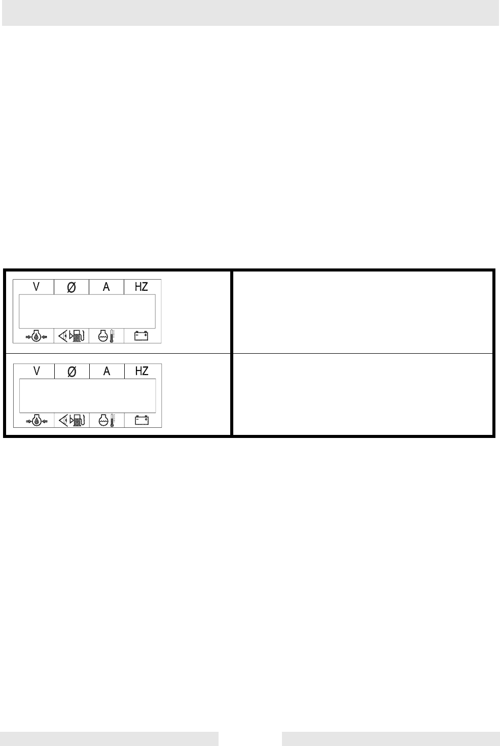
3.2 Generator Monitoring
Generator information is displayed on the top line of the LCD panel and
is scrolled continuously while the generator is operating, to show the
voltage, amperage and frequency of each phase.
Note: To prevent the display from scrolling, press the ENG HRS switch
down.
Volts “V”- Displays the AC output voltage being produced by the
generator.
Phase “Ø” - Indicates which phase is currently being displayed.
Amps “A” - Displays the AC output amperage produced by the
generator. If the generator is operating at no-load, output amperage
will display a 0.
Hertz “Hz” - Displays output frequency.
Sample display with engine running.
Sample display in “Auto” mode.
208 1 24 60
78 85% 175 14.3
UNIT IN AUTO
Ø 100% 85 13.2