www.wackergroup.
G 50/G 70/G 85 Table of Contents 1. Foreword 5 2. Safety Information 6 2.1 2.2 2.3 2.4 2.5 2.6 2.7 3. Operating Safety .................................................................................. 8 Service Safety .................................................................................... 10 Operator Safety while using Internal Combustion Engines ................ 11 Towing Safety .....................................................................................
Table of Contents 3.28 3.29 3.30 4. 47 Periodic Maintenance Schedule ..........................................................47 New Machines .....................................................................................48 Resetting the Periodic Maintenance Timer .........................................48 Air Cleaner ..........................................................................................49 Engine Lubrication .....................................................................
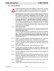
Foreword 1 Foreword This manual provides information and procedures to safely operate and maintain this Wacker model. For your own safety and protection from injury, carefully read, understand and observe the safety instructions described in this manual. Keep this manual or a copy of it with the machine. If you lose this manual or need an additional copy, please contact Wacker Corporation. This machine is built with user safety in mind; however, it can present hazards if improperly operated and serviced.
Safety Information 2. G 50/G 70/G 85 Safety Information This manual contains DANGER, WARNING, CAUTION, NOTICE and NOTE callouts which must be followed to reduce the possibility of personal injury, damage to the equipment, or improper service. This is the safety alert symbol. It is used to alert you to potential personal injury hazards. Obey all safety messages that follow this symbol to avoid possible injury or death.
G 50/G 70/G 85 Safety Information This machine is built with user safety in mind; however, like any electrical device it can present serious hazards if improperly operated and serviced. Follow instructions carefully! Should questions arise during operation or service of this equipment, contact Wacker Corporation. wc_si000158gb.
Safety Information 2.1 G 50/G 70/G 85 Operating Safety WARNING Familiarity and proper training are required for the safe operation of the machine. Machines operated improperly or by untrained personnel can be dangerous. Read the operating instructions contained in both this manual and the Engine Manual and familiarize yourself with the location and proper use of all controls. Inexperienced operators should receive instruction from someone familiar with the machine before being allowed to operate it. 2.
G 50/G 70/G 85 2.1.17 ALWAYS keep the area immediately surrounding and underneath the machine clean, neat, and free of debris and combustible materials. Make sure that the area overhead is clear of debris that could fall onto or into the machine or exhaust compartment. 2.1.18 ALWAYS be sure the machine is on a firm, level surface and will not tip, roll, slide, or fall while operating. 2.1.19 ALWAYS remove all tools, cords, and other loose items from the generator before starting it. 2.1.
Safety Information 2.2 G 50/G 70/G 85 Service Safety WARNING A poorly maintained machine can become a safety hazard! In order for the machine to operate safely and properly over a long period of time, periodic maintenance and occasional repairs are necessary. 2.2.1 NEVER perform even routine service (oil/filter changes, cleaning, etc.) unless all electrical components are shut down.
G 50/G 70/G 85 2.3 2.2.11 ALWAYS remain aware of moving parts and keep hands, feet, and loose clothing away from the moving parts of the machine. 2.2.12 ALWAYS replace all guards, fasten doors and make sure all safety devices operate properly after making repairs or servicing the equipment. 2.2.13 ALWAYS keep hands, feet, and loose clothing away from the moving parts on the generator and engine. 2.2.14 ALWAYS keep the machine clean and labels legible. Replace all missing and hard-to-read labels.
Safety Information 2.4 Towing Safety WARNING wc_si000158gb.fm G 50/G 70/G 85 Towing a large trailer requires special care. Both the trailer and vehicle must be in good condition and securely fastened to each other to reduce the possibility of an accident. 2.4.1 ALWAYS check that the hitch and coupling on the vehicle are rated equal to, or greater than, the trailer's “gross vehicle weight rating” (GVWR). 2.4.2 ALWAYS inspect the hitch and coupling for wear or damage.
G 50/G 70/G 85 2.5 Safety Information Reporting Trailer Safety Defects If you believe your trailer has a defect which could cause a crash or could cause injury or death, you should immediately inform the National Highway Traffic Safety Administration (NHTSA) in addition to notifying Wacker Corporation. If NHTSA receives similar complaints, it may open an investigation; and if it finds that a safety defect exists in a group of vehicles, it may order a recall and remedy campaign.
Safety Information 2.6 wc_si000158gb.
G 50/G 70/G 85 wc_si000158gb.
Safety Information 2.7 Ref. G 50/G 70/G 85 Safety and Operating Labels Label Meaning A ABSCHLEPPINSTRUKTIONEN 1. BETRIEBSVORSCHRIFT LESEN. 2. ANHANGEVORRICHTUNG VERWENDEN, DIE DER GESAMTBETRIEBSGEWICHTSKLASSE ENTSPRICHT. 3. ANHANGER SICHER AM ZUGFAHRZEUG BEFESTIGEN. 4. SICHERHEITSKETTEN KREUZWEISE ANBRINGEN. 5. ABREISSKETTE AM FAHRZEUG ANBRINGEN. 6. ANHANGERLEUCHTEN PRUFEN. INSTRUCCIONES DE REMOLQUE 1. LEA EL MANUAL DEL OPERARIO. 2.
G 50/G 70/G 85 Ref. Safety Information Label Meaning F DANGER! Asphyxiation hazard. Read the Operator’s Manual for instructions. No sparks, flames, or burning objects near machine. Stop the engine before adding fuel. Use only diesel fuel. G Tie-down point. H WARNING! To prevent hearing loss, wear hearing protection. Hand injury if entangled in moving belt. Rotating machinery! Do not reach inside with engine running. WARNING! Hot surface! CAUTION! Avoid spraying water into generator.
Safety Information Ref. G 50/G 70/G 85 Label Meaning L M Operator’s Manual must be stored on machine. Replacement Operator’s Manual can be ordered through your local Wacker distributor. a N wc_si000158gb.fm DANGER! Electric shock will cause serious injury or death.
G 50/G 70/G 85 Ref. Safety Information Label Meaning O WARNING! Generator can automatically start which can cause serious injury. Disconnect battery before servicing. P WARNING! Read and understand the supplied Operator’s Manual before operating the machine. Failure to do so increases the risk of injury to yourself or others. Q WARNING! To reduce the risk of electrical shock, read the operator’s manual.
Safety Information Ref. G 50/G 70/G 85 Label Meaning T WARNING! Disconnect battery before servicing. Read the Operator's Manual.
G 50/G 70/G 85 Ref. Safety Information Label Meaning Z Neutral bonded to frame. AA Fuses Read the operator's manual for machine information. 1 - Controller 2 - Not used 3 - Not used 4 - Not used BB WARNING! Electric shock at cooling fins. CC G 50 / G 70 / G 85 Generator and Receptacle Wiring wc_si000158gb.
Safety Information Ref. G 50/G 70/G 85 Label Meaning DD G 50 / G 70 - Engine Wiring G 70 w/ECU & G 85 - Engine Wiring EE WARNING! Hot surface! FF A nameplate listing the model number, item number, revision number, and serial number is attached to each unit. Please record the information found on this plate so it will be available should the nameplate become lost or damaged.
G 50/G 70/G 85 Ref. GG Safety Information Label Meaning CAUTION: Do not use battery disconnect switch while engine is running. Damage to electrical components may occur. CAUTION DO NOT USE THE BATTERY DISCONNECT SWITCH WHILE ENGINE IS RUNNING. DAMAGE TO THE ELECTRICAL COMPONENTS MAY OCCUR. VORSICHT .. .. BATTERIETRENNSCHALTER NICHT BENUTZEN, WAHREND MOTOR LAUFT! .. BESCHADIGUNG DER ELEKTRISCHEN BESTANDEILE KANN AUFTRETEN.
Operation 3. G 50/G 70/G 85 Operation 3.1 wc_tx000483gb.
G 50/G 70/G 85 Ref. Description Operation Ref.
Operation 3.2 G 50/G 70/G 85 Generator Monitoring Generator information is displayed on the top line of the LCD panel and is scrolled continuously while the generator is operating, to show the voltage, amperage and frequency of each phase. Note: To prevent the display from scrolling, press the ENG HRS switch down. Volts “V”- Displays the AC output voltage being produced by the generator. Phase “Ø” - Indicates which phase is currently being displayed.
G 50/G 70/G 85 3.3 Operation Engine Monitoring With the engine start switch set to “RUN/START” or “REMOTE START”, engine information will be continuously displayed on the bottom line of the LCD panel. OIL - Displays engine oil pressure. The gauge registers oil pressure between 0–100 psi. Normal operating pressure is between 60–80 psi. If oil pressure drops below 15 psi, the engine will automatically shut down. FUEL - Indicates the relative fuel level in the fuel tank.
Operation 3.4 G 50/G 70/G 85 Engine Shutdown Faults The engine control module (ECM) continuously monitors vital engine functions for fault conditions. When a fault condition occurs, the engine will shut down and the LCD panel will display the fault causing the shutdown. To reset the Engine Control Module and resume operation, return the Engine Start Switch manually to off “O”. Also refer to Section Warning Light. EMERGENCY STOP SPN.FMI 100.
G 50/G 70/G 85 Operation Normal operating pressure is between 40–80 psi. If oil pressure drops below 15 psi, the engine will automatically shut down. LOW OIL LEVEL For machines with the Low-Coolant Shutdown Option only. This fault will be displayed when the ECM has picked up a signal from the sensor that a low-coolant level exists. During such a condition, the ECM shuts the engine down. FAULT LOW WATER LEVEL 3.
Operation 3.7 G 50/G 70/G 85 Voltage Selector Switch See Graphic: wc_gr001682 The voltage selector switch is located in a separate enclosure on the generator on the opposite side of the machine. The selector switch is a three-position switch which mechanically changes the connections between the generator output leads and the terminal lugs on the generator. This allows three different volt ranges to be selected. 120/240 VAC 1Ø 120/208 VAC 3Ø 139/240 VAC 3Ø (Refer to Section Voltage Adjustment Rheostat.
G 50/G 70/G 85 3.8 Operation Emergency Stop Switch See Graphic: wc_gr001677 The emergency stop switch (p) is the red button located below the receptacle panel and can be accessed with the panel doors closed. Activate the emergency stop switch by pushing the red button in. Pushing the emergency stop switch opens the main circuit breaker and the fuel solenoid and results in the engine shutting down. The switch will remain in until the button is rotated and it pops out.
Operation 3.9 G 50/G 70/G 85 Main Line Circuit Breaker See Graphic: wc_gr002611 The main line circuit breaker (a) is located on the control panel. In the “off” position, this breaker interrupts power from the selector switch to the terminal lugs at the bottom of the generator panel. NOTICE: Before shutting down the generator or performing any service to the generator unit, make sure the main circuit breaker is in the off “O” position.
G 50/G 70/G 85 Operation 3.10 Engine Start Switch See Graphic: wc_gr002611 The engine start switch (f) is a three-position switch: “REMOTE START”, off “O”, and “START/RUN”. The “REMOTE START” position is the normal setting used when using the generator as a back-up power supply connected to a remote switch. In the REMOTE START position, the generator is in stand-by mode and will not start until the remote switch closes.
Operation G 50/G 70/G 85 3.13 Connection Lugs See Graphic: wc_gr002611 The customer connection lugs (r) are located on left at the bottom of the panel behind a hinged door. The lugs provide connection points for attachment of outside loads. A large label like the one shown in section Terminal Connections is attached to the inside of the terminal door. It shows the correct terminal connections for selected voltages.
G 50/G 70/G 85 Operation 3.14 Ground Connection See Graphic: wc_gr002611 A ground connection (s) is located next to the terminal lugs. The unit must have this ground lug connected to a good earthen ground for proper operating safety in compliance with NEC and local standards. 3.15 Convenience Receptacles See Graphic: wc_gr002611 The generator is equipped with two 120V/240V twist lock receptacles (l) rated at 50A, and one 120V/240V twist lock receptacles (m) rated at 30A.
Operation G 50/G 70/G 85 3.18 Terminal Connections ALL CONNECTIONS TO THE TERMINALS MUST BE MADE BY A TRAINED ELECTRICIAN. DANGER DANGER wc_tx000483gb.fm BACKFEED FROM THE GENERATOR INTO THE UTILITY’S DISTRIBUTION SYSTEM CAN CAUSE A SERIOUS INJURY OR DEATH TO UTILITY WORKERS! Improper connection of generator to a building’s electrical system can allow electrical current from the generator to backfeed into utility lines. This may result in electrocution of utility workers, fire or explosion.
G 50/G 70/G 85 Operation 3.19 Before Starting Before putting the generator into service, review each item on the following checklist. Because generators are often run for long periods of time unattended, it is important to make sure that the unit is set up properly to reduce possible problems. WARNING wc_tx000483gb.fm Failure to follow the procedures listed may cause injury to personnel or damage to the generator.
Operation G 50/G 70/G 85 3.20 Manual Start-up See Graphic: wc_gr001682, wc_gr001677, wc_gr002611 Before starting the generator set, thoroughly review the pre-start-up checklist in the previous section. Proceed with generator start-up only after checking each item in that section. Thoroughly read and make sure you understand the engine Operator’s Manual supplied with the generator. Follow the steps below and the illustration on the opposite page in the order listed.
G 50/G 70/G 85 Operation 3.20.7 After engine starts, allow it to warm up for a few minutes and check readouts on LCD panel. The “TIME TO SERVICE” interval will be displayed. Make sure battery charging system, oil pressure and engine temperature readings are within normal ranges. 3.20.8 Check that AC voltage is correct. Voltage can be fine-adjusted by turning the voltage adjustment rheostat (b) on the metering panel. 3.20.9 Check frequency. Under no-load conditions, frequency should read around 61.
Operation G 50/G 70/G 85 3.21 Running the Generator See Graphic: wc_gr002611 Leave the Engine Start Switch (f) in the “START/RUN” position while the generator is operating. If the generator was started using a remote switch, leave Engine Start Switch in the “REMOTE START” position. Let the generator run for a few minutes to warm engine before closing main circuit breaker.
G 50/G 70/G 85 Operation 36 34 32 30 28 26 Engine Power Deration (%) 24 22 20 18 16 14 12 10 8 6 4 2 0 7 (2,1) 8 (2,4) 9 (2,75) 10 (3,0) 11 (3,3) 12 (3,6) 13 (4,0) 14 (4,3) Altitude x 1000 Feet wc_tx000483gb.
Operation G 50/G 70/G 85 3.23 Shutting Down Generator Check with other personnel on the jobsite and let them know that power is being turned off. Make sure that the power shutdown will not create any hazards by turning off devices such as pumps, heaters, or lights that may need to be kept on. 3.23.1 Remove all loads from generator. 3.23.2 Open (turn to off “O”) main line circuit breaker. 3.23.3 Let engine run for approximately 5 minutes to allow it to cool down. 3.23.
G 50/G 70/G 85 Operation 3.28 Automatic/Remote Start-up See Graphic: wc_gr002611 In the “REMOTE START” position the generator can be started remotely, either through a transfer switch or some other type of remote start switch. “REMOTE START” is the normal setting when using the generator as a standby power supply. Before placing the generator in the automatic start-up mode, review the pre-start and manual Start-up sections in this manual and follow procedure below.
Operation G 50/G 70/G 85 3.29 Remote/Transfer Switch See Graphic: wc_gr002611 When the generator is used as a standby power supply, it must be equipped with a device which isolates it from the utility’s distribution system.
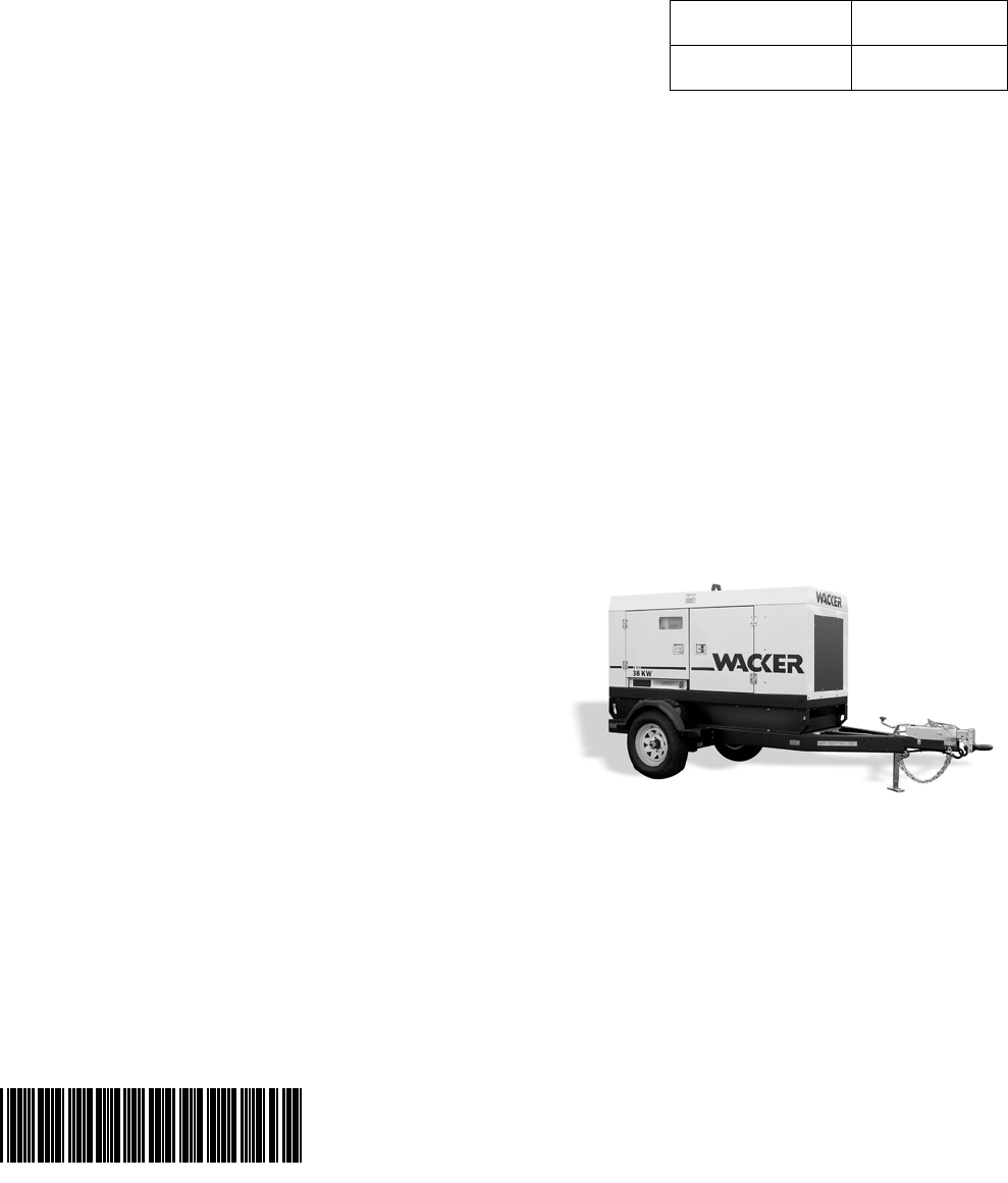
G 50/G 70/G 85 Operation 3.30 Towing See Graphic: wc_gr000510 The generator trailer is equipped with brakes, lights, and coupler connection. Before towing the generator, perform the following: 3.30.1 Check that the towing vehicle and hitch have a rating equal to or greater than the GVWR. Refer to the Technical Data. 3.30.2 Check the condition of both the coupler and hitch. DO NOT tow the trailer if the coupler or hitch is damaged. 3.30.3 Make sure that the hitch and coupler are compatible.
Operation G 50/G 70/G 85 d c a b w c _ g r0 0 0 5 1 0 wc_tx000483gb.
G 50/G 70/G 85 4. Maintenance Maintenance 4.1 Periodic Maintenance Schedule The Periodic Maintenance Schedule below lists basic maintenance intervals for the engine and generator. For detailed maintenance procedures on the engine, refer to the engine Operator's Manual.
Maintenance 4.2 4.3 G 50/G 70/G 85 New Machines 4.2.1 Run generator at least 60–100% of continuous load for the first 100 hours. 4.2.2 Change engine oil and replace oil filter after the first 50 hours. Resetting the Periodic Maintenance Timer After maintenance has been performed on the generator, it is necessary to reset the periodic maintenance timer. • If the periodic maintenance timer is at zero, press the ENG. HRS switch UP and hold for 10 seconds until the “TIME TO SERVICE” resets to 250 hours.
G 50/G 70/G 85 4.4 Maintenance Air Cleaner See Graphic: wc_gr000511 Replace the air filter cartridge when yellow indicator of the engine air filter gauge reaches the red line. The air cleaner assembly contains a one-piece single element air filter cartridge (c). To replace the air filter cartridge: • Remove the end cover (d), then discard the entire air filter cartridge.
Maintenance 4.5 G 50/G 70/G 85 Engine Lubrication Check engine oil daily before starting engine. DO NOT operate engine if oil level is below ADD mark on dipstick. Always keep oil level within the crosshatch pattern or “full” mark on dipstick. Change oil after first 100 hours of operation and every 250 hours thereafter. Refer to the engine manufacturer’s Operator’s Manual for lubrication specifications. Break-in Service 4.5.1 This engine is factory-filled with John Deere Engine Break-in Oil.
G 50/G 70/G 85 4.6 Engine Coolant WARNING 4.7 Maintenance Check the coolant level of the radiator with the engine cold. After initial filling of radiator to 3/4" below bottom of filler neck, maintain proper level in overflow bottle daily. NEVER remove radiator cap or drain plug while engine is hot! Pressurized coolant can cause serious burns. Shut off engine. Only remove radiator cap when it is cool enough to touch with bare hands.
Maintenance 4.8 G 50/G 70/G 85 Troubleshooting Automatic Shutdown There are several automatic shutdown conditions: low oil pressure, high coolant temperature, engine overspeed, engine underspeed, engine overcrank, and low fuel. When these occur, the operator can perform certain diagnostic tests to help identify the problem. Most of these diagnostics deal with the engine. The generator, however, can also cause problems.
G 50/G 70/G 85 Maintenance Overspeed or Underspeed Shutdown Restart engine and read the AC frequency meter. Meter should read 60 Hz under no-load condition. Overcrank Shutdown 4.8.1 Check fuel level. 4.8.2 Check for proper operation of fuel pump. 4.8.3 If engine still does not start, refer to engine manufacturer’s Operator’s Manual or Service Manual for possible engine problems. Low Fuel Level Shutdown 4.8.1 Check fuel level. Note: Warning light will come on when fuel level drops below 25%.
Maintenance G 50/G 70/G 85 4.
4 3 6 5 4 2 1 3 2 1 L1 L2 L3 CT1 CT2 CT COMMON CT3 42 43 41 37 38 36 39 Y BR OR W Y BR OR W L 36A SHUNT CT-3 L/W CT-1 CT-2 36B MAIN BRKR LUG SAFETY LIMIT SWITCH L3 2/0 CT-3 PAIR BLK 4 GA L2 2/0 CT-2 PAIR BLK 4 GA L1 2/0 CT-1 PAIR BLK 4 GA N BOND BAR G R1 R2 B B B B N G B B B B 6GA 7 4 6 5 3 15 13 10 18 1 8 2 16 14 11 12 9 17 GROUND TO ENCLOSURE BOX STUD 4 3 2 1 T2 7 8 4 5 1 2 8 7 6 5 B B B B B B 12 11 10
Maintenance G 50/G 70/G 85 BOM Revision See Graphic: Revision See Graphic: Revision See Graphic: 0009366 123 & higher wc_gr004692 106–122 wc_gr003171 105 & lower wc_gr002614 0009367 124 & higher wc_gr004692 106–123 wc_gr003171 105 & lower wc_gr002614 0009369 124 & higher wc_gr004692 106–123 wc_gr003171 105 & lower wc_gr002614 0009467 131 & higher wc_gr004692 107–130 wc_gr003171 106 & lower wc_gr002614 0009468 133 & higher wc_gr004692 107–132 wc_gr003171 106 & lower
G 50/G 70/G 85 wc_tx000484gb.
Maintenance G 50/G 70/G 85 4.11 Trailer Wiring Ref. Description 1 Front right side amber light 2 Front left side amber light 3 Trailer plug 4 Battery 5 Brake solenoid 6 Right rear taillight 7 License plate holder lights 8 Left rear taillight 9 Rear right side red light 10 Rear left side red light Ref.
G 50/G 70/G 85 Maintenance Standard and Hydraulic Brakes Electric Brakes 1 9 Br W Br W W R R 3 5 W R G Y Br W G Br W + W R R R 5 7 Br 7 Y Br W 8 Br W Br W 10 2 wc_tx000484gb.
Maintenance G 50/G 70/G 85 4.12 G 50/G 70 Engine Wiring BOM Revision See Graphic: Revision See Graphic: Rev.
wc_tx000484gb.
Maintenance G 50/G 70/G 85 BOM Revision See Graphic: Revision See Graphic: Rev.
G 50/G 70/G 85 Maintenance G 50/G 70 Engine Wiring wc_tx000484gb.
Maintenance G 50/G 70/G 85 BOM Revision See Graphic: Revision See Graphic: Rev.
G 50/G 70/G 85 Maintenance G 50/G 70 Engine Wiring wc_tx000484gb.
Maintenance G 50/G 70/G 85 BOM Revision See Graphic: Revision See Graphic: Rev.
G 50/G 70/G 85 Maintenance G 50/G 70 Engine Wiring wc_tx000484gb.
Maintenance G 50/G 70/G 85 4.13 G 85 & G 70 w/ECU Engine Wiring BOM Revision See Graphic: Revision See Graphic: 0009369 124 & higher wc_gr004614 123 & lower wc_gr002616 0009459 133 & higher wc_gr004614 132 & lower wc_gr002616 0620003 129 & higher wc_gr004614 128 & lower wc_gr002616 0620350 wc_gr004614 0620351 wc_gr004614 0620352 wc_gr004614 Engine Ref. Description Ref.
wc_tx000484gb.
Maintenance G 50/G 70/G 85 BOM Revision See Graphic: Revision See Graphic: 0009369 124 & higher wc_gr004614 123 & lower wc_gr002616 0009459 133 & higher wc_gr004614 132 & lower wc_gr002616 0620003 129 & higher wc_gr004614 128 & lower wc_gr002616 0620350 wc_gr004614 0620351 wc_gr004614 0620352 wc_gr004614 Engine Ref. Description Ref.
G 50/G 70/G 85 wc_tx000484gb.
Factory-Installed Options 5 Mobile Generators Factory-Installed Options This machine may be equipped with one or more of the following factory-installed options. To verify if any of these options are installed on your machine, contact the WACKER Corporation at 1-800-770-0957. A nameplate listing the Model Number, Item Number, Revision, and Serial Number is attached to each unit. Please have this information available when contacting WACKER Corporation. 5.
Mobile Generators 5.2 Factory-Installed Options Fuel/Water Separator See Graphic: wc_gr001705 The fuel/water separator separates water from the fuel on models with Isuzu engines. Empty the separator water bowl (a) as needed by opening the water bowl drain (b). The separator element should be changed each time the fuel filter is changed—approximately every 600 hours of operation. To change the element: wc_tx000380gb.fm 5.2.
Factory-Installed Options 5.3 Mobile Generators Electronic Governor See Graphic: wc_gr001714, wc_gr001715, wc_gr001716, wc_gr001717 The electronic governor option consists of an electronic module (a or b) and an electronic actuator (c or d). The module senses rotation of the flywheel, then sends a signal to the electronic actuator that governs the fuel injection system. The system is designed to precisely regulate engine rpm, and thus frequency, to within approximately 0.25%.
Mobile Generators 5.4 Factory-Installed Options LCD Strip Heater See Graphic: wc_gr001724, wc_gr001725 The LCD strip heater option includes a thermostat module (a) and a clear heater strip that is bonded to the LCD (b) of the ECM. The purpose of the strip heater is to prevent the LCD from being damaged by extremely cold temperatures. The resistance of the coiled element of the heater is sensed by the thermostat. The resistance of the element changes with temperature.
Factory-Installed Options 5.5 Mobile Generators Low Coolant Shutdown See Graphic: wc_gr001708 The low-coolant shutdown system consists of an electronic sensor that monitors coolant level. The sensor (a) is mounted to the radiator and wired into the ECM. The sensor probe (b) is submerged in radiator coolant. If the probe senses no coolant, it sends a signal to the ECM. The ECM program includes a 10-second timer to protect from nuisance shutdowns.
Mobile Generators 5.6 Factory-Installed Options Lube Level Maintainer See Graphic: wc_gr001711, wc_gr001712, wc_gr001713 The lube level maintainer system protects the engine from low oil levels by providing an additional 6-quart oil reservoir. Oil from the reservoir is gravity-fed from the oil reservoir (a) through the control valve (b) and into the engine oil pan as needed. The valve includes a sightglass (c) through which the oil level can be seen.
Factory-Installed Options 5.7 Mobile Generators Temperature-Activated Shutters See Graphic: wc_gr001706, wc_gr001707 The shutters (a) are mounted to the top of the generator enclosure. The shutters are designed to keep the engine compartment warm, thus increasing engine temperature during cold weather operation. The shutters are activated through a wax-pellet actuator (b) that is connected to the generator's cooling system.
Mobile Generators Factory-Installed Options Notes: wc_tx000380gb.
Factory-Installed Options 5.9 Mobile Generators Wiring Diagram 1 Or R R R B R 11 R B+ 86 2 3 10 R 82 4 Bl G 83 B 4 84 82 85 83 9 81 11 NC B 81 5 80 W 80 Y 91 90 C NO R Or 91 87 87 8 89 R R 7 6 – 88 B W B 90 89 88 wc_gr001868 12 Wire Colors B Black R Red Y Yellow Or Orange G Green T Tan Br Brown Pr Purple L Blue V Violet Cl Clear Sh Shield P Pink W White Gr Gray LL Light blue wc_tx000380gb.
Mobile Generators Factory-Installed Options 5.10 Wiring Diagram Components See Graphic: wc_gr001868 Ref Description Ref Description 1 Thermostat module 7 Positive air shutoff solenoid actuator 2 Terminal block 8 Auxiliary relay terminals 3 1 Amp fuse 9 Plug 1, engine sensor inputs 4 Water level sensor 10 Electronic control board 5 Lube level maintainer low level switch 11 LCD heater 6 30 Amp circuit breaker 12 Positive air shutoff relay module wc_tx000380gb.
Factory-Installed Options Mobile Generators 5.11 Cam-Lock See Graphic: wc_gr002584 A second optional outlet panel features cam-lock connectors (u) for easy tool changes. The door is equipped with an interlock switch (q). When the door is opened this switch automatically trips the main circuit breaker. wc_tx000380gb.
Mobile Generators Factory-Installed Options 5.12 Containment System See Graphic: wc_gr002647 Overspills and leaks are captured in the containment system. The containment system holds over 110% of the fluid contained in the machine. The containment system should be checked every 50 hours or 2 weeks and drained when necessary. If fluid is found in the containment tank, trace the cause of the leak and correct.
Technical Data 6. G50 /G 70/G 85 Technical Data 6.1 Engine Data Item Number: G 50 0009366 0009467 0620001 Rev. 112 & lower G 70 0009367 0009468 0620002 Rev. 113 & lower G 70 0620350 0620352 G 85 0009369 0009459 0620003 Rev. 114 & lower Engine Engine make / type John Deere / 4.5L Model 4045DF270 4045TF270 Number of cylinders 4045TF285 4 Displacement l (in3) Engine speed rpm 4.5 (274.6) 1800 Power @ 1800 rpm kW/Hp Coolant capacity l (qts.) Oil capacity l (qts.) 15 (15.
G50 /G 70/G 85 Technical Data Item Number: G 50 0620001 Rev. 113 & above G 70 0620002 Rev. 114 & above G 70 0620351 G 85 0620003 Rev. 115 & above Engine Engine make / type John Deere / 4.5L Model 4045DF270 4045TF270 Number of cylinders 4045TF285 4 Displacement l (in3) Engine speed rpm 4.5 (274.6) 1800 Power @ 1800 rpm kW/Hp Coolant capacity l (qts.) Oil capacity l (qts.) 15 (15.9) Volts/ CCa 12/1000 Battery 50/67 74.5/100 74/99 84.2/113 22.7 (24) 22.7 (24) 26.5 (28) 22.
Technical Data 6.2 G50 /G 70/G 85 Generator Data Item Number: G 50 0009366 0009467 0620001 G 70 0009367 0009468 0620002 G 70 0620350 0620351 0620352 G 85 0009369 0009459 0620003 Generator Make/Type Mecc Alte / Brushless Model Generator speed ECO32-3S/4 ECO32-2L/4 3 position AC voltages available 120/240 zig-zag 120/208 low-wye 277/480 Hi-wye Frequency 60 Hz 1.0 0.8 1ø 3ø Voltage regulation ±1.00% Insulation class Sound level at 7 m (23 ft.
G50 /G 70/G 85 6.3 Technical Data Trailer and Skid Data Item Number: G 50 0009366 G 50 0009467 0620001 G 70 0009367 G 70 0009468 0620002 G 70 0620350 G 70 0620351 0620352 G 85 0009369 G 85 0009459 0620003 Trailer and Skid Dry weight of skid kg (lbs.) Operating weight of skid kg (lbs.) Trailer weight kg (lbs.
Technical Data 6.
Wacker Construction Equipment AG · Preußenstraße 41 · D-80809 München · Tel.: +49-(0)89-3 54 02 - 0 · Fax: +49 - (0)89-3 54 02-3 90 Wacker Corporation · P.O. Box 9007 · Menomonee Falls, WI 53052-9007 · Tel. : (262) 255-0500 · Fax: (262) 255-0550 · Tel. : (800) 770-0957 Wacker Asia Pacific Operations · Skyline Tower, Suite 2303, 23/F · 39 Wang Kwong Road, Kowloon Bay, Hong Kong · Tel.