www.wackergroup.com 0154607en 0403 Generator G 3.
DANGER CARBON MONOXIDE Using a generator indoors CAN KILL YOU IN MINUTES. Generator exhaust contains carbon monoxide (CO). This is a poison you cannot see or smell. If you can smell the generator exhaust, you are breathing CO. But even if you cannot smell the exhaust, you could be breathing CO. • NEVER use a generator inside homes, garages, crawlspaces, or other partly enclosed areas. Deadly levels of carbon monoxide can build up in these areas.
G 3.3AE Table of Contents 1. Foreword 3 2. Safety Information 4 3. 4. 2.1 Laws Pertaining to Spark Arresters ...................................................... 4 2.2 Operating Safety .................................................................................. 5 2.3 Operator Safety while using Internal Combustion Engines .................. 6 2.4 Service Safety ...................................................................................... 7 2.5 Label Locations ............
Table of Contents 5. G 3.3AE Maintenance 5.1 5.2 5.3 5.4 5.5 5.6 5.7 5.8 5.9 5.10 5.11 5.12 24 Engine Maintenance ............................................................................24 Periodic Maintenance Schedule ..........................................................24 Engine Oil ............................................................................................25 Air Cleaner ..........................................................................................26 Spark Plug ..
Foreword 1. Foreword This manual provides information and procedures to safely operate and maintain this Wacker model. For your own safety and protection from injury, carefully read, understand and observe the safety instructions described in this manual. Keep this manual or a copy of it with the machine. If you lose this manual or need an additional copy, please contact Wacker Corporation. This machine is built with user safety in mind; however, it can present hazards if improperly operated and serviced.
Safety Information 2. G 3.3A Safety Information This manual contains DANGER, WARNING, CAUTION, and NOTE callouts which must be followed to reduce the possibility of personal injury, damage to the equipment, or improper service. This is the safety alert symbol. It is used to alert you to potential personal injury hazards. Obey all safety messages that follow this symbol to avoid possible injury or death.
G 3.3A 2.2 Safety Information Operating Safety BACKFEED FROM THE GENERATOR INTO THE PUBLIC POWER DISTRIBUTION SYSTEM CAN CAUSE SERIOUS INJURY OR DEATH TO UTILITY WORKERS! DANGER Improper connection of generator to a building's electrical system can allow electrical current from the generator to backfeed into utility lines. This may result in electrocution of utility workers, fire, or explosion.
Safety Information 2.3 2.2.11 ALWAYS transport generator in an upright position. 2.2.12 ALWAYS keep machine at least one meter (three feet) away from structures, buildings and other equipment during use. 2.2.13 ALWAYS keep the area immediately surrounding the generator clean, neat and free of debris. Make sure that the area overhead is clear of debris that could fall onto or into the generator, or exhaust compartment. 2.2.
G 3.3A 2.4 Safety Information Service Safety WARNING wc_si000053gb.fm Poorly maintained equipment can become a safety hazard! In order for the equipment to operate safely and properly over a long period of time, periodic maintenance and occasional repairs are necessary. If the generator is experiencing problems or is being serviced, attach a "DO NOT START" sign to the control panel to notify other people of its condition. 2.4.
Safety Information 2.5 G 3.3A Label Locations D A N G E R G E F A H R P E L IG R O S T O P 2 - 1 5 1 1 5 6 GND 88897 D A N G E R wc_gr000675 wc_si000053gb.
G 3.3A 2.6 Safety Information Safety and Operating Labels Wacker machines use international pictorial labels where needed. These labels are described below: Label Meaning D A N G E R G E F A H R P E L IG R O S T O P D A N G E R DANGER! Engines emit carbon monoxide; operate only in well ventilated area. Read the operator's manual. No sparks, flames or burning objects near machine. Shut off engine before refueling. DANGER! Electric shock hazard. Read operator’s manual for instructions.
Safety Information G 3.3A Label Meaning 1 2 5 3 6 1 4 3 2 Open main circuit breaker. Open fuel flow valve. Close choke. Push or turn engine switch to ON position. Pull rewind starter. Press engine crank switch to "CRANK" position. Open choke. wc_si000053gb.
G 3.3A Safety Information Label Meaning Close main circuit breaker. Push or turn engine switch to OFF position. Press engine crank switch to "OFF" position. Close fuel flow valve. 2 - 1 5 1 1 5 6 Potential Earth - Hook up cable from grounding rod to this point. Guaranteed sound power level in dB(A). wc_si000053gb.
Safety Information G 3.3A Label Meaning MENOMONEE FALLS, WI USA 53051 Model Rev. Serial No. hz lbs kW class V N/M A GENERATING SET ISO 8528 MADE IN USA Insul. Class Man. Yr. 110635 Item No. kg A nameplate listing the Model Number, Item Number, Revision, and Serial Number is attached to each unit. Please record the information found on this plate so it will be available should the nameplate become lost or damaged.
G 3.3A 3. Technical Data Technical Data 3.1 Generator Item No. G3.3AE 0008259 Generator Output Type AC Voltages Available Frequency Power Factor AC receptacles 3.3 kVA Single voltage, single phase, brush-type system 230 / 1ø volts / phase Hz 50 cos Ø 1.0 2 / 16 qty / amp Main Circuit Breaker amp 15 Dimensions mm 685 x 585 x 530 Weight (dry) Kg 71 wc_td000056gb.
Technical Data 3.2 G 3.3A Engine Item No. G3.3AE 0008259 Engine Engine Make Honda Engine Model GX 240 K1 QA2 Rated Power 4.8 kW Spark Plug NGK BPR 6ES Electrode Gap mm 0.7 - 0.8 Engine Speed - full load rpm 3000 ± 100 Engine Speed - no load rpm 3100 ± 100 Air Cleaner type Dual element Engine Lubrication oil grade Engine Oil Capacity SAE 10W30 service class SG or SF 1100 ml Fuel type Regular unleaded gasoline Fuel Tank Capacity liters 19.5 liters/hr. 2.
G 3.3A 4. Operation Operation 4.1 Application and Power Requirements This generator is designed to operate single-phase, 50 Hz appliances running at 230 VAC. CAUTION: Do not exceed the power output of the generator. Damage to tools or generator will occur. See Technical Data. Check the nameplate or label provided on tools and appliances to make sure their power requirements are met by the power output of the generator.
Operation 4.2 Indoor Installation DANGER 4.3 G 3.3A If the generator must be installed indoors, adequate ventilation or exhaust hoses must be provided. When venting exhaust fumes, make sure the exhaust piping is large enough to prevent excessive back pressure to the engine. Back pressure reduces engine efficiency and may cause the engine to overheat. Exhaust gas from the engine contains poisonous carbon monoxide gas; exposure to carbon monoxide can cause loss of consciousness and may lead to death.
G 3.3A 4.4 Operation Grounding the Generator See Graphic: wc_gr000544 The generator should be grounded to a good ground source in compliance with state and local regulations. Use 10 mm2 wire and secure one end to the ground terminal (a) provided on the generator frame and the other end to a suitable ground source. = w c _ g r0 0 0 5 4 4 wc_tx000150gb.
Operation 4.5 G 3.3A Generator Derating All generators are subject to derating for altitude and temperature. Internal combustion engines, unless modified, run less efficiently at higher altitudes due to the lack of air pressure. This translates into a lack of power and thus reduction in generator output. Temperature affects both engine and generator performance. As temperature increases, an engine will run less efficiently and the more resistance will be found in electrical components.
G 3.3A Operation 4.6 Use of Extension Cords WARNING When a long extension cord is used to connect an appliance or tool to the generator, a voltage loss occurs—the longer the cord, the greater the voltage loss. This results in less voltage being supplied to the appliance or tool and increases the amount of current draw or reduces performance. A cord with a larger cross section will reduce the voltage loss. CAUTION: Operating equipment at low voltage can cause it to overheat.
Operation 4.7 G 3.3A Earth-leakage Circuit Breaker See Graphic: wc_gr000661 Generator models ending with an “AE” are equipped with an earthleakage circuit breaker. The circuit breaker is current-operated and shuts off the power to the receptacles when a ground fault of 30 milliAmps or greater occurs in the generator or to a piece of equipment attached to the generator. The circuit breaker is located on the control panel and should be tested for proper operation every time the generator is used.
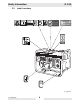
G 3.3A 4.8 Operation Control Panel See Graphic: wc_gr000679 The generator is protected by a 15 amp circuit breaker (a) located on the control panel. The circuit breaker protects the generator from severe overloads or short circuits. If the circuit breaker opens, turn the engine off immediately and determine the cause before restarting.
Operation 4.9 wc_tx000150gb.fm G 3.3A Before Starting 4.9.1 Read and understand safety and operating instructions at beginning of this manual. 4.9.2 Read and understand the meanings of all warning and operating labels. 4.9.3 Check: • oil level in engine. • fuel level. • condition of air cleaner. • tightness of external fasteners. • condition of fuel lines.
G 3.3A Operation 4.10 To Run See Graphic: wc_gr000679 and wc_gr000665 4.10.1 Disconnect all loads from the generator and place main circuit breaker lever in open position (O). 4.10.2 Open fuel valve by moving lever to the right (a1). 4.10.3 If engine is cold, move choke lever to closed position (b1). If engine is hot, set choke to open position (b2). 4.10.4 Turn engine switch to "ON" (c1) and pull starter rope (d). Note: If the oil level in the engine is low, the engine will not start.
Maintenance 5. G 3.3A Maintenance 5.1 Engine Maintenance The chart below lists basic machine and engine maintenance. Refer to engine manufacturer’s Operator’s Manual for additional information on engine maintenance. 5.2 Periodic Maintenance Schedule Daily before starting Check fuel level. • Check engine oil level. • Inspect air filter. Replace as needed. • Check and tighten external hardware. • After first 20 hrs. Clean air cleaner element.* Every 50 hrs. Every 100 hrs. Every 300 hrs.
G 3.3A 5.3 Maintenance Engine Oil See Graphic: wc_gr000022 5.3.1 Drain oil while the engine is still warm. 5.3.2 Remove the oil fill plug (a) and drain plug (b) to drain oil. Note: In the interests of environmental protection, place a plastic sheet and a container under the machine to collect any liquid which drains off. Dispose of this liquid in accordance with environmental protection legislation. wc_tx000161gb.fm 5.3.3 Install drain plug. 5.3.
Maintenance 5.4 G 3.3A Air Cleaner See Graphic: wc_gr000025 The engine is equipped with a dual element air cleaner. Service air cleaner frequently to prevent carburetor malfunction. CAUTION: NEVER run engine without air cleaner. Severe engine damage will occur. NEVER use gasoline or other types of low flash point solvents for cleaning the air cleaner. A fire or explosion could result. WARNING To service: wc_tx000161gb.fm 5.4.1 Remove air cleaner cover (a).
G 3.3A 5.5 Maintenance Spark Plug See Graphic: wc_gr000028 Clean or replace spark plug as needed to ensure proper operation. Refer to the engine Owner’s Manual. The muffler becomes very hot during operation and remains hot for a while after stopping the engine. Do not touch the muffler while it is hot. WARNING Note: Refer to the Technical Data for the recommended spark plug type and the electrode gap setting. 5.5.1 Remove spark plug and inspect it. 5.5.
Maintenance 5.6 G 3.3A Cleaning the Sediment Cup See Graphic: wc_gr000029 5.7 5.6.1 Turn fuel valve off. 5.6.2 Remove sediment cup (a) and O-ring (b). 5.6.3 Wash both thoroughly in a nonflammable solvent. Dry and reinstall them. 5.6.4 Turn fuel valve on and check for leaks. Carburetor Adjustment See Graphic: wc_gr001061 The pilot screw (a) is fitted with a limiter cap to prevent excessive enrichment of the air-fuel mixture in order to comply with emission regulations.
G 3.3A 5.8 Maintenance Engine Speed See Graphic: wc_gr000114 Adjust engine to the no load or idle speed per the Technical Data. 5.8.1 Start the engine and allow it to warm up to normal operating temperature. 5.8.2 Turn the throttle stop screw (a) in to increase speed, out to decrease speed. Make sure the throttle lever is touching the stop screw before measuring rpm. a wc_gr000114 wc_tx000161gb.
Maintenance 5.9 G 3.3A Storage Before storing generator for a long period of time: 5.9.1 Close the fuel valve and remove and empty sediment cup under carburetor. 5.9.2 Disconnect the fuel line from the carburetor. Place open end of fuel line into a suitable container and open fuel valve to drain fuel from tank. Gasoline is extremely flammable. Drain fuel tank in a well ventilated area. DO NOT drain tank in an area with flames or sparks. WARNING 5.9.
G 3.3A Maintenance 5.11 Troubleshooting Problem / Symptom Reason / Remedy If engine doesn't start, check that: • Engine switch is on "Start". • Fuel valves under fuel tank and on engine are open. • Fuel tank has fuel. • Choke lever is in correct position. Choke should be closed when starting a cold engine. • All loads are disconnected from generator. • Spark plug is in good condition. • Spark plug cap is tight. • Engine oil level is adequate.
Maintenance 5.12 G 3.3A Wiring Schematic See Graphic: wc_gr000680 Ref. Description A Generator Ref. Description Ref. Description Ref. B Control Box C Ref. Description Engine Description 1. Main stator winding 7. RFI suppressor 2. Main circuit breaker 8. Rotor winding 3. Earth-leakage circuit breaker (“AE” models only) 9. Automatic voltage regulator 4. 16A receptacle 10. Ignition switch 5. Choke 11. Oil level switch 6. Auxilliary winding 12.
EC DECLARATION OF CONFORMITY CE-KONFORMITÄTSERKLÄRUNG DECLARACIÓN DE CONFORMIDAD DE LA CE DÉCLARATION DE CONFORMITÉ C.E.
Wacker Construction Equipment AG · Preußenstraße 41 · D-80809 München · Tel.: +49-(0)89-354 02 - 0 · Fax: +49 - (0)89-354 02-390 Wacker Corporation · P.O. Box 9007 · Menomonee Falls, WI 53052-9007 · Tel. : +1-(1)(262) 255-0500 · Fax: +1-(1)(262) 255-0550 · Tel. : (800) 770-0957 Wacker Asia Pacific Operations · Sunley Center, Unit 912, 9/F · 9 Wing Qin Street, Kwai Chung, N.T. · Hong Kong · Tel.