0212727en 002 05.
Inhalt Contents 1 Foreword .................................................................................................................... 5 2 Introduction ............................................................................................................... 6 2.1 Means of representation for this operator's manual ........................................... 6 2.2 WACKER representative .................................................................................... 7 2.
Contents 8 Maintenance ............................................................................................................ 37 8.1 Maintenance schedule ..................................................................................... 37 8.2 Maintenance work ............................................................................................ 38 9 Troubleshooting ...................................................................................................... 40 10 Disposal ....
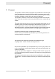
Foreword 1 Foreword This operator's manual contains information and procedures for the safe operation and maintenance of your WACKER machine. In the interest of your own safety and to prevent accidents, you should carefully read through the safety information, familiarize yourself with it and observe it at all times. This operator's manual is not a manual for extensive maintenance and repair work. Such work should be carried out by WACKER Service or authorized specialists.
Introduction 2 Introduction 2.1 Means of representation for this operator's manual Warning symbols This operator's manual contains safety imformation of the categories: DANGER, WARNING, CAUTION, NOTICE. They should be followed to prevent danger to life and limb or damage to equipment or improper service. DANGER This warning notice indicates hazards that result in serious injury or even death. f Danger can be avoided by the following the actions mentioned.
Introduction 2.2 WACKER representative Depending on your country, your WACKER representative is your WACKER Service, your WACKER affiliate or your WACKER dealer. You can find the addresses in the Internet at www.wackergroup.com. The addresses of the WACKER main locations are located at the end of this operator's manual. 2.3 Described machine parts This operator's manual is valid for different machine parts from a product range.
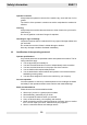
Safety information 3 EHB 11 Safety information 3.1 Principle State of the art This machine has been constructed with state-of-the-art technology according to the recognized rules of safety. Nevertheless, when used improperly, dangers to the life and limb of the operator or to third persons or damage to the machine or other materials cannot be excluded. Proper use The machine must only be used for the following purposes: To drill holes with a diameter ranging from 12 to 125 mm.
EHB 11 Safety information Maintenance Regular maintenance is required in order for the machine to operate properly and reliably over time. Neglected maintenance work can make the machine dangerous to use. Strictly observe the prescribed maintenance intervals. Do not use the machine if it requires maintenance or repairs. Malfunctions If you detect a malfunction, you must shut down and secure the machine immediately.
Safety information EHB 11 Operator's controls Always keep the operator's controls of the machine dry, clean and free of oil or grease. The function of the operator's controls must not be manipulated or rendered ineffective. Cleaning Always keep the machine clean and be sure to clean it each time you have finished using it. Do not use gasoline or solvents. Danger of explosion! Checking for signs of damage Inspect the machine when it is switched off for any signs of damage at least once per work shift.
EHB 11 3.3 Safety information Protective gear Work clothing Clothing should be appropriate, i.e. should be close-fitting but not restrict your movement. When on construction sites, do not wear long hair loosely, loose clothing or jewelry including rings. These objects can easily get caught or be drawn in by moving machine parts. Personal protective gear Wear personal protective gear to avoid injuries or health hazards: Non-skid, hard-toed shoes. Work gloves made of durable material.
Safety information 3.5 EHB 11 Operating safety Work environment Familiarize yourself with your work environment before you start work. This includes e.g. the following items: Obstacles in the work and traffic area. Load-carrying capacity of the ground. The measures needed to cordon off the construction site from public traffic. The measures needed to secure walls and ceilings. Options available in the event of an accident.
EHB 11 Safety information Caution with toxic materials Some materials may contain toxic chemicals which are released during demolition. Therefore personal protective equipment must be worn to prevent inhalation of and skin contact with work dust. Do not direct towards people Do not direct the machine towards people in the vicinity during oepration. The tool might be flung out and cause serious injuries.
Safety information 3.7 EHB 11 Safety during the operation of electric appliances Specific regulations for electrical appliances Observe the safety information provided in the brochure General Safety Rules which is included in the scope of delivery of your machine. Also observe the country-specific regulations, standards and guidelines in reference to accident prevention in connection with electrical equipment and machines.
EHB 11 Safety information Protecting from moisture Protect the machine against rain, snow or any other forms of moisture. This could cause damage or malfunctions. 3.8 Maintenance Maintenance work Service and maintenance work must only be carried out to the extent described in these operating instructions. All other procedures must be performed by your WACKER representative. For further information, refer to chapter Maintenance.
Safety information 3.9 EHB 11 Safety labels Your machine has adhesive labels containing the most important instructions and safety information. Make sure that all the labels are kept legible. Replace any missing or illegible labels. For the following machines: 0008733, 0008742, 0008745 Item Label Description 1 CAUTION Prevent loss of control and injury use both hands when operating drill. 2 WARNING Do not operate without safety guards. Read and understand instruction book.
EHB 11 Safety information For all other machines: Item Label Description 1 Sound power level 17
Scope of delivery 4 EHB 11 Scope of delivery Item Designation 1 Carrying case with tool compartments 2 Grease gun 3 Rotary hammer 4 Operator's manual 5 Parts book General safety information (without illustration) 18
EHB 11 5 Description Description 5.1 Application A wide selection of easily interchangeable tools is available for drilling holes from 12 to 125 mm suitable for breaking, chiseling, digging, puddling, hammering, ramming and deburring. The machine is suited for processing natural as well as synthetic stone and asphalt and any type of masonry and concrete. 5.2 Functionality Principle The machine is a demolition hammer with a pneumatic percussion system as well as an additional drilling function.
Description 5.3 EHB 11 Components and operator's controls Item Designation 1 Tool holder 2 ON/OFF switch 3 Thumbwheel for pre-selecting speed 4 Adjusting lever for chiseling/ hammer drilling 5 Supplementary handle 6 Adjustable depth gauge Tool holder The machine is available with three different tool holders: SDS-max Hexagonal with locking strap Spline shaft ON/OFF switch A start-up protection is linked with the ON/OFF switch.
EHB 11 Description Thumbwheel for pre-selecting speed Use the thumbwheel to pre-select the speed. Reducing the speed while in percussion operating mode diminishes the percussion forces as required for removing tiles, for example. Adjusting lever for chiseling/hammer drilling The adjusting lever for chiseling/hammer drilling has three positions as listed below. The arrow on the housing and the opposite symbol on the adjusting lever indicate the selected operating mode.
Description EHB 11 Supplementary handle Item Designation 1 Offset handle (not present on all machines) 2 Radial handle 3 Clamping wheel (not present on all machines) 4 Clamping piece The Pro-Ergo® supplementary handle can be adjusted to various positions to ensure safe working conditions and reduce operator fatigue. The offset and the radial handle are part of the supplementary handle. Adjustment options: The entire supplemental handle can be swiveled variably by 360°.
EHB 11 6 Transport Transport Transporting the machine The machine must be transported in the carrying case supplied. 1. Remove tool. 2. Turn the offset handle to the back (not present on all machines). 3. If mounted on housing, unscrew radial handle and screw onto supplementary handle. 4. Place the machine in the carrying case. 5. Wind up the power cable and place in the carrying case. Note: Do not kink the power cable! 6. Store the tools in the carrying case. 7.
Operation 7 EHB 11 Operation WARNING Improper handling can result in injury or serious material damage. f Read and follow all safety instructions of this operator's manual, see chapter Safety information. 7.1 Prior to starting the machine After unpacking, the machine is ready for operation. Plug The machine comes with a country-specific plug as a standard equipment. Checking the machine f Check the machine and all components for damages.
EHB 11 Operation 7.2 Adjusting the machine 7.2.1 Operating mode Selecting the operating mode WARNING Starting the machine during switching! Danger of injury with uncontrolled start up. f Actuate adjusting lever for chiseling/hammer drilling only after machine has come to a complete standstill. Item 1 Designation Adjusting lever for chiseling/ hammer drilling Check position of adjusting lever for chiseling/hammer drilling.
Operation 7.2.2 EHB 11 Speed/rpm Adjusting the speed Item 1 Designation Thumbwheel for pre-selecting speed Use the thumbwheel to adjust the speed: f Turn the thumbwheel for pre-selecting the speed counterclockwise (-) to reduce the speed. f Turn the thumbwheel for pre-selecting the speed clockwise (+) to increase the speed.
EHB 11 7.2.3 Operation Supplementary handle Adjusting the supplementary handle Only operate the machine with the supplementary handle. The illustration below depicts the adjustment options. Adjusting the offset handle Note: The offset handle is not present for all machines. Item Designation 1 Offset handle 2 Clamping wheel 1. Loosen the clamping wheel by turning counterclockwise. 2. Swivel offset handle to desired position (take note of lock-in positions). 3.
Operation EHB 11 Changing position of the radial handle Item 1 Designation Radial handle 1. Remove the radial handle by turning it counterclockwise. 2. Attach radial handle to desired position (supplementary handle or housing) using screw.
EHB 11 Operation Swiveling the supplementary handle Item Designation 1 Radial handle 2 Hexagonal bolt 3 Clamping piece 4 Allen wrench 1. Remove the radial handle by turning it counterclockwise. 2. Use the Allen wrench integrated into the radial handle to loosen the hexagonal bolt at the clamping piece. 3. Swivel supplementary handle to desired position. 4. Tighten the hexagonal bolt again. 5. Attach radial handle to desired position (supplementary handle or housing) using screw.
Operation 7.2.4 EHB 11 Adjustable depth gauge Adjusting the depth gauge Item Designation 1 Wing bolt 2 Adjustable depth gauge 1. Loosen the wing bolt. 2. Adjust depth gauge as needed by pulling out or pushing in. 3. Retighten the wing bolt firmly.
EHB 11 Operation 7.3 Changing tools 7.3.1 General instructions General notes Tools are easily changed with all tool holders without requiring additional tools. Only use tools with intact shanks. Before inserting the tool, ensure that the tool is sufficiently sharpened and that it is suitable for the intended application. 7.3.2 Tool holder SDS-max Inserting tool Item Designation 1 Tool 2 Tool holder 1. Clean tool end. 2. Insert tool into tool holder. 3.
Operation EHB 11 Removing tool Item Designation 1 Tool 2 Locking sleeve 1. Slide locking sleeve towards rear. The lock releases. 2. Remove tool from tool holder by pulling forward.
EHB 11 7.3.3 Operation Tool holder for tool with hexagonal bolt Inserting tool Item Designation 1 Tool 2 Retaining spring 1. Clean tool end. 2. Swivel out retaining spring. 3. Push tool into the tool holder as far as it will go. 4. Return retaining spring to original position. 5. Check to see if the tool is locked by pulling on the tool. Removing tool 1. Swivel out retaining spring. 2. Remove tool from the tool holder. 3. Return retaining spring to original position.
Operation 7.3.4 EHB 11 Tool holder for tool with spline shaft Inserting tool Item Designation 1 Tool 2 Lock bolt 1. Clean tool end. 2. Turn lock bolt by 90°. 3. Push tool into the tool holder as far as it will go. When inserting a chisel, make sure the notch on the tool points towards the spline shaft. 4. Turn lock bolt back by 90°. 5. Check to see if the tool is locked by pulling on the tool. Removing tool 1. Turn lock bolt by 90°. 2. Remove tool from the tool holder. 3.
EHB 11 7.4 Operation Starting up Connecting the machine to the power supply The machine may only be connected to AC single phase, connection values see chapter Technical Data. NOTICE Electrical voltage. Incorrect voltage can cause damage on the machine. f Check if the voltage of the current source corresponds with the information of the machine, see chapter Technical Data. WARNING Electrical voltage. Injuries from electrocution. f Check power cable and extension cable for signs of damage.
Operation EHB 11 Switching on the machine WARNING Injuries from insufficiently guided or uncontrolled machine. f Always hold machine with both hands and stand firmly. Item 1 Designation ON/OFF switch f Press the ON/OFF switch. 7.5 Decomissioning Switching off the machine 1. Release ON/OFF switch. 2. Wait until the machine has come to a complete standstill. 3. Set down the machine in such a way that it cannot tilt, fall or slip. 4. Pull the plug from the plug receptacle.
EHB 11 8 Maintenance Maintenance WARNING Improper handling can result in injury or serious material damage. f Read and follow all safety instructions of this operator's manual, see chapter Safety information. 8.1 Maintenance schedule Task Daily before operation Check power cable for perfect condition – if power cable is defective, have it replaced. * Visual inspection of all parts for damage. Clean the machine.
Maintenance 8.2 EHB 11 Maintenance work WARNING Electrical voltage. Injuries from electrocution. f Remove the plug from the plug receptacle before all work on the machine. Work in the workshop Perform maintenance work in a workshop on a workbench. This has the following benefits: Protection of the machine of contamination on the construction site. A level and clean work surface makes work easier. There is a better overview over small parts and they are not lost as easily. Cleaning the machine 1.
EHB 11 Maintenance Checking the tool holder for wear Item Value A 200 mm B Max. 6 mm f Measure the tool play 200 mm from insertion point. Play may not exceed 6 mm. If the play exceeds 6 mm, the tool holder bushing in the tool holder must be replaced.
Troubleshooting 9 EHB 11 Troubleshooting Please refer to the following table if the machine does not work properly. It contains potential faults, their causes and remedies. Malfunction Cause Remedy Machine not in operation For machines with 230 V: Input voltage too high (> 300 V) or too low (< 80 V). Provide correct voltage; if necessary use an extension cable with sufficient cross section. For machines with 115 V: Input voltage too high (> 150 V) or too low (< 45 V).
EHB 11 Disposal 10 Disposal Dispose the machine and packaging through environmentally friendly recycling. During disposal observe the regional rules and regulations, e.g. the European Directive for obsolete electrical and electronic devices. Do not dispose of the machine in household rubbish. It must be disposed of separately.
Accessories EHB 11 11 Accessories There is a wide range of accessories available for the machine. For more information on the individual accessories, visit the following website: www.wackergroup.com.
EHB 11 Technical data 12 Technical data 12.1 EHB 11 BL/BLM - 230 Designation Unit Item no. EHB 11 BL EHB 11 BLM 0008395 0008919 0008740 0008754 0610233 0008731 0008920 0008743 0008997 0610234 Length x Width x Height mm (in) 560 x 105 x 245 (22.0 x 4.1 x 9.7) 620 x 105 x 245 (24.4 x 4.1 x 9.7) Weight kg (lb) 11 (24.3) 11.7 (25.8) Rated voltage V 220-240 1~ Rated frequency Hz 50-60 Rated power consumption kW 1.38 Rated current consumption A 7.
Technical data 12.2 EHB 11 EHB 11 BL/BLM - 115 Designation Unit Item no. EHB 11 BL EHB 11 BLM 0008733 0008741 0008744 0008745 Length x Width x Height mm (in) 560 x 105 x 245 (22.0 x 4.1 x 9.7) 620 x 105 x 245 (24.4 x 4.1 x 9.7) Weight kg (lb) 11 (24.3) 11.7 (25.8) Rated voltage V 110-127 1~ Rated frequency Hz 50-60 Rated power consumption kW 1.2 Rated current consumption A 13 Minimum generator output requirement for single connection kW 3.
EHB 11 12.3 Technical data EHB 11 BLS - 115 Designation Unit Item no. * EHB 11 BLS 0008742 Length x Width x Height mm (in) 620 x 105 x 245 (24.4 x 4.1 x 9.7) Weight kg (lb) 11.5 (25.4) Rated voltage V 110-127 1~ Rated frequency Hz 50-60 Rated power consumption kW 1.2 Rated current consumption A 13 Minimum generator output requirement for single connection kW 3.
Technical data 12.4 EHB 11 Notes regarding class rating Class rating The class rating according to DIN EN 61140 specifies the safety measures for electrical equipment to avoid electrocution. There are four class ratings: Class rating Meaning 0 No special protection apart from the basic insulation. No grounded conductor. Plug connection without grounded conductor contact. I Connection of all conductive housing components to the grounded conductor. Plug connection with grounded conductor contact.
EHB 11 12.5 Technical data Extension cable A permitted extension cable must fulfill the following criteria: The extension cable must be undamaged. The extension cable has to be connected correctly on plug and bushing. The extension cable has to be suitable for use at construction sites: Average rubber hose H05RN-F or better – WACKER recommends H07RN-F or a country-specific equivalent design. The extension cable must have been checked by a qualified electrician.
Technical data EHB 11 Extension cable for the US market: Voltage [V] Extension [ft] Cross-section area of cable [AWG] 110–130 < 36 14 < 58 12 < 89 10 < 75 16 < 121 14 < 190 12 < 302 10 220–240 Example You utilize an EHB 11 BLM/230 and want to use an extension cable with a length of 50 m (164 ft). The machine has an input voltage of 230 V. According to the table, the extension cable must feature a cross-section area of 4.0 mm2 (AWG 12).
EC Declaration of Conformity Wacker Construction Equipment AG, Preußenstraße 41, 80809 München certifies that the construction machines: Category: Demolition/rotary hammer Type EHB 11 BL EHB 11 BL/BLM EHB 11 BLS Machine type number 0008395, 0008733, 0008740, 0008741, 0008745, 0008919, 0610233 0008731, 0008743, 0008744, 0008754, 0008920, 0008997, 0610234 0008742 11 11.7 11.
DIN EN ISO 9001 Certificate Prüf- und Zertifizierungsinstitut VERBAND DER ELEKTROTECHNIK ELEKTRONIK INFORMATIONSTECHNIK e.V. CERTIFICATE Registration-Number: 6236/QM/06.97 This is to certify that the company Wacker Construction Equipment AG Wacker-Werke GmbH & Co.
Wacker Construction Equipment AG, Preußenstraße 41, 80809 München – Deutschland – Tel.: +49-(0)89-354 02-0 – Fax: +49-(0)89-354 02-390 Wacker Corporation – P.O. Box 9007 – Menomonee Falls, WI 53052-9007 – USA – Tel.: +1(1)262-255-0500 – Fax: +1(1)262-255-0550 – Support: 800-770-0957 Wacker Machinery (HK) Ltd.– Skyline Tower, Suite 2303, 23/F – 39 Wang Kwong Road, Kowloon Bay – Hong Kong – Tel.