
Installation & Assembly


WAC Lighting
www.waclighting.com
Phone (800) 526.2588 • Fax (800) 526.2585
Headquarters/Eastern Distribution Center
44 Harbor Park Drive • Port Washington, NY 11050
Phone (516) 515.5000 • Fax (516) 515.5050
Western Distribution Center
1750 Archibald Ave • Ontario, CA 91761
Phone (800) 526.2588 • Fax (800) 526.2585
WAC Lighting retains the right to modify the design of our products at any time as part of the company's continuous improvement program. JULY, 2014
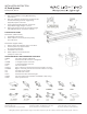
INSTALLATION INSTRUCTION
J2 Track Systems
J2-T4, J2-T8, J2-T12
SAFETY INSTRUCTION
• Read all of these instructions before installing the track system.
• Turn o power at main switch before installing or modifying the system.
• Do not install within six inches of any curtain or combustible materials.
• Do not install less than 5 feet above a oor.
• Do not install in damp or wet locations.
• Do not install concealed, or extended through building walls.
• Do not attempt to energize anything other than a track light xture.
• Do not connect a track to more than one branch circuit. Although track light systems may seem to operate acceptably,
a dangerous overload of the neutral may occur and result in a risk of re.
• Check with a qualied electrician before wiring.
• All installation shall be in accordance with NEC and all local codes
• Save these installation instructions and refer to them when additions or changes to the track conguration are made.
JUNCTION BOX ELECTRICAL FEED
1. Parts J2-LE and J2-UCP are needed for junction box
installation. Attach cross bar (supplied) to the junction box
with two screws (supplied).
2. Mount track to ceiling or wall.
(See Track Mounting Instructions.)
LIVE END FEED
1. Insert live-end into track with arrow on live-end pointing
toward polarity groove on track.
2. Remove live-end cover. Route wire through the
live-end knock out hole. Secure wire connector
to live end connector.
3. Fasten positive wire (hot wire) to gold screw terminal
marked “P1”. Fasten the second positive wire to the gold
screw terminal marked “P2”.
4. Fasten neutral wire to silver screw terminal marked “N”.
5. Fasten ground wire (may be green or bare wire) from ceil-
ing to green ground screw terminal on live-end.
6. Replace live-end cover and secure with screw.
7. Tighten track to ceiling.
NOTE: DIMMING
Two-circuit track requires grounded neutral type dimmer
switches.