
Installation Sheet

dweLED retains the right to modify the design of our products at any time as part of the company's continuous impro
vement program. Feb 2019
dweLED.com
Phone (800) 526.2588
Fax (800) 526.2585
Headquarters/Eastern Distribution Center
44 Harbor Park Drive
Port Washington, NY 11050
Central Distribution Center
1600 Distribution Ct
Lithia Springs, GA 30122
Western Distribution Center
1750 Archibald Avenue
Ontario, CA 91760
2
INSTALLATION INSTRUCTIONS
949-LED Pendant
PD-94940
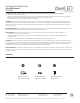
Fixture Wires
Black or
Smooth
Fixture Wires
White or
Ribbed
Fixture Wires
Bare wire
(Ground)
House Wires
Black
(Hot)
House Wires
White
(Neutral)
House Wires
Green or Bare Copper
(Ground)
FIG. 2 Wiring
FIG. 1
PREPARATION
1. Shut off the power at the circuit breaker and remove existing fixture,
including the crossbar.
2. Carefully unpack your new fixture and lay out all the parts on a clear
area. Be careful not to lose any small parts necessary for installation.
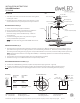
MOUNTING THE FIXTURE (Fig. 1)
3. Remove the mounting screw (C) from the fixture.
4. Choose the number of down rods suitable of your application.
5. Thread the fixture wire through the rods and canopy.
Connect the canopy, down rod and fixture body. Make sure
all are tightened.
6. Secure the mounting back plate to the junction box using the
screws provided with the junction box.
NOTE: The side of the mounting plate marked “GND” must face out.
CONNECTING THE WIRES (Fig. 2)
7. Connect the driver input/output wires with junction box wires as shown (
Fig.2). Make sure that all wire connectors (A) (B) are secure. If
your outlet box has a green or bare copper ground wire, connect the fixture’s ground wire to it. Otherwise, connect the fixture’s ground
wire directly to the mounting plate using the green screw provided. After wires are connected, tuck them carefully inside the junction box.
NOTE: This fixture features electronic low voltage (ELV or TRAIC) or 0-10V dimming capabilities. See notes below for specific dimming
wiring information.
8. Place the fixture over the mounting back plate and secure it with mounting screws (C).
9. Rotate the three rings in a circumferential direction to keep the lamp in balance.
NOTE: DIMMING WIRING INSTRUCTIONS (Fig. 3)
11. To utilize ELV or TRAIC dimming: use black (hot), white (neutral) and bare copper ground wir se (ground).
12. To utilize 0-10V dimming: use purple (dim+), gray (dim-), black (hot), white (neutral) and bare copper ground wire (ground)
NOTE: Make sure to connect 0-10V
Back Plate Dimensions FIG. 3
White - Neutral
Black - Hot
Purple - Dim+
Gray - Dim-
Red - Fixture+
Black - Fixture-
A
Wire Connector
Ground Wire
Junction Box
C
Mounting Screw
Wire Connector
B
To Fixture
Mounting Plate
6
″
Rod
3-12
″
Rod
Driver
(3 6/8
″
L×3 6/8
″
W×5/8
″
H)
Junction Box Screw
Fixture
1 3/8”
5 3/4”
1 3/4”
prior to powering up the fixture in order to allow the 0-10V dimming to function properly.