
Installation Sheet

WAC Lighting
www.waclighting.com
Phone (800) 526.2588 • Fax (800) 526.2585
Headquarters/Eastern Distribution Center
44 Harbor Park Drive • Port Washington, NY 11050
Phone (516) 515.5000 • Fax (516) 515.5050
Western Distribution Center
1750 Archibald Ave • Ontario, CA 91761
Phone (800) 526.2588 • Fax (800) 526.2585
WAC Lighting retains the right to modify the design of our products at any time as part of the company's continuous improvement program. JULY, 2017 1
INSTALLATION INSTRUCTION
Lucio LED Monopoint
MO-6010/MO-6022
SAFETY INSTRUCTION
IMPORTANT: NEVER attempt any work without shutting o the electricity.
- Read all instructions before installing.
- System is intended for installation by a qualied electrician in accordance with the National Electrical Code and local regulations.
- Go to the main fuse box, or circuit breaker. Place the main power switch in the “OFF” position and unscrew the fuse(s) or switch “OFF”
the circuit breaker switch(es) that control the power to the xture or room that you are working on.
- Place the wall switch in the “OFF” position.
AVERTISSEMENT
IMPORTANT : Coupez l’électricité avant TOUTE manipulation.
- IMPORTANT : Coupez l’électricité avant TOUTE manipulation.
- Lisez toutes les instructions avant d’installer.
- Système est destiné à être installé par un électricien qualié en conformité avec le code national de l’électricité et les règlements locaux.
- Accédez au panneau central de disjoncteurs ou de fusibles de votre demeure et placez l’interrupteur principal en Position d’arrêt (« OFF »).
- Placez l’interrupteur mural en position d’arrêt (« OFF »).
All parts must be used as indicated in these instructions. Do not substitute any parts, leave parts out, or use any parts that are
worn out or broken. Failure to follow this instruction could invalidate the UL listing of this xture.
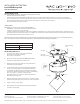
INSTALLING LAMP (FIG.1)
1.
Loosen the three canopy screws, twist and separate
the canopy cover from the base plate.
(keep screws on base plate)
2. Remove the knock out marked with “WIRING HOLE” label
from the base plate.(Another KO is not for use)
3. Attach the base plate to the surface by using slotted holes
for mounting screws (supplied).
4. Connect xture wires to building wires. This xture features
electronic low voltage (ELV) or 0-10V dimming capabilities.
To utilize ELV, wire black (line hot) and white (line neutral) in
accordance to dimmer specications. To utilize 0-10V dimming,
wire 0-10V+ (dim+), 0-10V- (dim-), black (line hot),
white (line neutral) in accordance to dimmer specications.
Green xture wire to ground.
5. Align the wiring hole on the canopy to the one on the base plate
and mount it by twisting key holes over three screws in base plate.
6. Tighten screws to secure canopy.
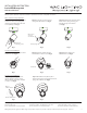
7. After the light is on, rotate the luminaire body horizontally or
vertically to aim properly.
Electrical Data
INPUT VOLTAGE 120-277V AC, 50/60Hz
DIMMING ELV, 0-10V
Base Plate
Base Plate
Mounting Screw
Canopy Mounting
Screw
Fig.1
NOT FOR USE
365°
Canopy
90°