
Installation Sheet

WAC Lighting
www.waclighting.com
Phone (800) 526.2588 • Fax (800) 526.2585
Headquarters/Eastern Distribution Center
44 Harbor Park Drive • Port Washington, NY 11050
Phone (516) 515.5000 • Fax (516) 515.5050
Western Distribution Center
1750 Archibald Ave • Ontario, CA 91761
Phone (800) 526.2588 • Fax (800) 526.2585
WAC Lighting retains the right to modify the design of our products at any time as part of the company's continuous improvement program. JUNE, 2014
INSTALLATION INSTRUCTION
Rubix - LED Ceiling Mount
FM-W2510
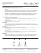
PREPARATION
1. Shut o the power at the circuit breaker and
remove existing xture, including the crossbar.
2. Carefully unpack your new xture and lay out all the
parts on a clear area. Be careful not to lose any small
parts necessary for installation.
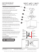
MOUNTING THE FIXTURE (Fig. 1)
3. Drill holes in the ceiling aligned with hole location
in the mounting plate (D1). Insert the mounting anchors (I1).
4. Secure mounting plate (D1) to the junction box (F1) using
junction box screws (B1).The side of the mounting plate
marked “GND” (E1) must face out.
Then using wood screws(H1) to reinforce the mounting plate.
5. Fasten the wood screws (H1) into the mounting anchors (I1).
Tighten the mounting plate (D1) on the ceiling.
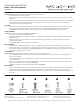
CONNECTING THE WIRES (Fig. 2)
6. Connect the electrical wires as shown in Fig. 2, making sure
that all wire connectors (A1) are secured. If your outlet box has a
green or bare copper ground wire, connect the xture’s ground
wire to it. Otherwise, connect the xture’s ground wire directly
to the backplate (D1) using the green screw (E1) provided. After
wires are connected, tuck them carefully inside the junction box.
7. This xture is dimming with electronic low voltage dimmer
switch, and also can be dimming with 0-10V dimmer switch. If
needed, connect the brown (BR or +) / blue (BL or -) wires of the
driver with the supplied 0-10V dimmer switch (not provided).
8. Place the xture over the mounting plate and secure with
screws (C1) and gasket (G1).
9. The xture can be mounted onto the wall as a sconce
if desired.
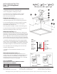
COMPLETING THE INSTALLATION (Fig. 3)
10.To prevent moisture from entering the outlet box and
causing a short, use clear caulking (i.e. indoor/outdoor silicone
sealant) to outline the outside of xture backplate where it
meets the wall. If use as a wall sconce, leave a space at bottom
to allow moisture a means to escape (Fig.3).
100%10% DIMMING
COMPATIBLE WITH THE FOLLOWING ELECTRONIC
LOW VOLTAGE ELV DIMMERS
LUTRON DVELV-300P ,SELV-300P
LEVITON VPE04,IPE04
FIG.2
Fixture Wires
Black or
Smooth
Fixture Wires
White or
Ribbed
Fixture Wires
Bare Copper
(Ground)
House Wires
Black
(Hot)
House Wires
White
(Neutral)
House Wires
Green or Bare Copper
(Ground)
B1D1
F1
A1
I1
E1
H1
G1
C1