
Installation Sheet

www.dweLED.com
Phone (800) 526.2588
Fax (800) 526.2585
Headquarters/Eastern Distribution Center
44 Harbor Park Drive
Port Washington, NY 11050
Central Distribution Center
1600 Distribution Ct
Lithia Springs, GA 30122
Western Distribution Center
1750 Archibald Ave
Ontario, CA 91761
dweLED retains the right to modify the design of our products at any time as part of the company's continuous improvement program. Jan 2019 3
INSTALLATION INSTRUCTIONS
969-LED Flush Mount
FM-96916/FM-96922/FM-96928
Fig.1
PREP
ARATION
1. Shut off the power at the circuit breaker and remove existing fixture, including the crossbar.
2. Carefully unpack your new fixture and lay out all the parts on a clear area. Be careful not to lose any small parts necessary for
installation.
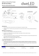
MOUNTING THE FIXTURE (Fig. 1)
3.
Remove the mounting screw (B) and mounting plate from the fixture.
4. Drill holes in the wall aligned with the key holes located on the back plate, insert the plastic anchor (D),
NOTE: FM-96916 skips this step.
5. Secure the mounting plate to the junction box using the screws provided with the junction box. Fasten the back plate to the wall
with the plastic anchors using the wood screws (C) provided.
NOTE: The side of the mounting plate marked “GND” must face out.
6. Hook the safety cord to the mounting plate.
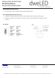
CONNECTING THE WIRES (Fig. 2)
7. Connect the driver’s input wires to junction box wires as shown (Fig. 2). Make sure that all wire connectors (A) are secure. If
your outlet box has a green or bare copper ground wire, connect the fixture’s ground wire to it. Otherwise, connect the fixture’s
ground wire directly to the back plate using the green screw provided. After wires are connected, tuck them carefully inside the
junction box.
NOTE: This fixture features electronic low voltage (ELV ) dimming capabilities.