
Installation Sheet

Phone (800) 526.2588
Fax (800) 526.2585
44 Harbor Park Drive
Port Washington, NY 11050
1600 Distribution Ct
Lithia Springs, GA 30122
1750 Archibald Avenue
Ontario, CA 91760
2
INSTALLATION INSTRUCTION
FM-67116
1. Shut o the power at the circuit breaker and remove existing xture, including the crossbar.
2. Carefully unpack your new xture and lay out all the parts on a clear area. Be careful not to lose any small parts necessary for installation.
3. Remove the mounting screw (B) from the xture, take down the lamp shade.
4. Loose the assemble screw from the xture back plate, but let the assemble screw stay on the mounting plate. Rotate the mounting ring
until it can be taken down.
5. Secure the mounting ring to the junction box using standard junction box screws that comes with the junction box.
(i)using any other non-original-manufacturer provided junction box screw may result in safety issue;
(ii) The side of the mounting ring marked “GND” must face out.
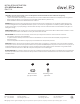
6. Connect the driver’s input wires to junction box wires as shown (Fig. 2). Make sure that all wire connectors (A) are secure. If your outlet box
has a green or bare copper ground wire, connect the xture’s ground wire to it. Otherwise, connect the xture’s ground wire directly to the
back plate using the GND screw provided. After wires are connected, tuck them carefully inside the junction box.
7. Place the xture back plate slot through the assemble screw, slide the xture back plate until the assemble screw head on the small end of
the xture back plate slot, then screw down the assemble screw.
8. Secure the xture to the mounting back plate using the mounting screw (B).
Black or
Smooth
White or
Ribbed
Bare wire
(Ground)
Black
(Hot)
White
(Neutral)
Green or Bare Copper
(Ground)
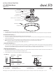
Ø4"
1 3/4"
G
N
D
1 3/8"
Mounting Screw
Mounting Ring
B
Junction Box
Wire Connector
A
Lamp Shade
Driver(3 1/2"Lx3 3/8"Wx5/8"L)
Junction Box Screw
Assemble Screw
Fxture Back Plate