
Installation Sheet

2WAC Lighting retains the right to modify the design of our products at any time as part of the company's continuous improvement program.
waclighting.com
Phone (800) 526.2588
Fax (800) 526.2585
Headquarters/Eastern Distribution Center
44 Harbor Park Drive
Port Washington, NY 11050
Central Distribution Center
1600 Distribution Ct
Lithia Springs, GA 30122
Western Distribution Center
1750 Archibald Avenue
Ontario, CA 91760
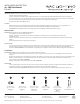
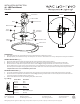
FIG. 1
Wire Connector
Back Plate Dimensions
Junction
Box Screw
Fixture
Frame
UNLOCK
LOCK
Mounting Back Plate
Junction Box
Ground Wire
Wood
Screw
Plastic
Anchor
Wire
Connector
Driver
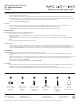
E1
D1
B1
F1
A1
C1
Fixture Wires
Black or
Smooth
Fixture Wires
White or
Ribbed
Fixture Wires
Bare wire
(Ground)
House Wires
Black
(Hot)
House Wires
White
(Neutral)
House Wires
Green or Bare Copper
(Ground)
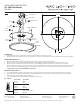
Fig. 2 Wiring
PREPARATION
1. Shut o the power at the circuit breaker and remove existing xture, including the crossbar.
2. Carefully unpack your new xture and lay out all the parts on a clear area. Be careful not to lose any small parts necessary for installation.
CONNECTING THE WIRES (Fig. 2)
3. Remove the xture frame from the mounting plate by rotating the xture frame counterclockwise.
4. Drill holes in the ceiling or wall aligned with the key holes located in the mounting back plate, insert the plastic anchors (D1).
5. Connect the driver's input wires to junction box wires as shown in Fig. 2, making sure that all wire connectors (A1) are secured.
If your outlet box has a green or bare copper ground wire, connect the xture's ground wire to it. Otherwise, connect the xture's ground
wire directly to the back plate using the green screw provided. After wires are connected, tuck them carefully inside the junction box.
*Requires Driver to be recessed within the junction box
MOUNTING THE FIXTURE (Fig. 1)
6. Secure the mounting back plate to the junction box using junction box screws (B1), fasten it to the wall using the wood screws (E1).
7. Connect the driver's output wire to the xture as shown in Fig. 2, making sure that all wire connectors (B1) are secured. After wires are
connected, tuck them carefully inside the junction box.
8. Twist-lock the xture frame onto the mounting back plate until secured.
INSTALLATION INSTRUCTION
46 - LED Flush Mount
FM-4622
Ø
21 3/4"
3 3/4"
1 3/8"
1 3/4"
1 5/8"