
Installation Sheet

dweLED.com
Phone (800) 526.2588
Fax (800) 526.2585
Headquarters/Eastern Distribution Center
44 Harbor Park Drive
Port Washington, NY 11050
Central Distribution Center
1600 Distribution Ct
Lithia Springs, GA 30122
Western Distribution Center
1750 Archibald Avenue
Ontario, CA 91760
2
INSTALLATION INSTRUCTION
FM-27214\FM-27218
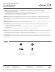
Fixture Wires
Black or
Smooth
Fixture Wires
White or
Ribbed
Fixture Wires
Bare wire
(Ground)
House Wires
Black
(Hot)
House Wires
White
(Neutral)
House Wires
Green or Bare Copper
(Ground)
1. Shut o the power at the circuit breaker and remove
existing xture, including the crossbar.
2. Carefully unpack your new xture and lay out all the parts on a clear area.
Be careful not to lose any small parts necessary for installation.
3. Loosen the mounting screw (B) from the xture, and remove the mounting back plate.
4. Secure the mounting back plate to the junction box using standard junction box screws that comes with the junction box.
(i)using any other non-original-manufacturer provided junction box screw may result in safty issue.
(ii) The side of the mounting plate marked “GND” must face out.
5. Properly secure the safety cord to the bracket on mounting back plate to temporary hang the xture in place.
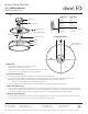
6. Connect the driver’s input wires to junction box wires as shown (Fig. 2). Make sure that all wire connectors (A) are secure. If your outlet
box has a green or bare copper ground wire, connect the driver’s ground wire to it. Otherwise, connect the xture’s ground wire directly
to the back plate using the green screw provided. After wires are connected, tuck them carefully inside the junction box.
7. Secure the xture by mounting the canopy to the mounting back plate. Turn and rotate the canopy in the direction of the arrow until
it stops. Fasten the canopy to the mounting back plate using the mounting screw (B).
Mounting Screw
Wire Connector
A
B
Driver
Safety Cords
Fixture
Canopy
Junction box
Mounting back plate
Junction Box Screw
FM-27214: Ø12 1/8"
FM-27218: Ø16 1/8"
1 3/4"
1 3/8"