
Installation Sheet

WAC Lighting
www.waclighting.com
Phone (800) 526.2588 • Fax (800) 526.2585
Headquarters/Eastern Distribution Center
44 Harbor Park Drive • Port Washington, NY 11050
Phone (516) 515.5000 • Fax (516) 515.5050
Western Distribution Center
1750 Archibald Ave • Ontario, CA 91761
Phone (800) 526.2588 • Fax (800) 526.2585
WAC Lighting retains the right to modify the design of our products at any time as part of the company's continuous improvement program. MAY, 2016
Fixture Wires
Black or
Smooth
Fixture Wires
White or
Ribbed
Fixture Wires
Bare wire
(Ground)
Fixture Wires
Violet (Dim +)
Gray (Dim -)
(use with 0-10V dimmer)
House Wires
Black
(Hot)
House Wires
White
(Neutral)
House Wires
Green or Bare Copper
(Ground)
House Wires
Brown
Blue
Fig. 1
Fig. 2 Fig. 3
FEATURES:
• Electronic short circuit, over current, over voltage, over temperature protection with auto-reset.
• Class 2, UL listed
• Suitable for damp locations
• 0-10V dimmable
PREPARATION:
• Shut o the power at the circuit breaker.
• Carefully unpack your new xture and lay out all the parts on a clear area. Be careful not to lose any small parts necessary for installation.
• Transformer is to be installed away from heat sources and accessible for service.
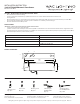
INSTALLATION: (FIG.1)
1. Loosen two cover screws (B1) and remove the cover (C1).
2. Identify which xture is to be used with transformer. For invisiLED tapelight (LED-T24, LED-T24L, LED-TX24, LED-TE24),
use with preinstalled 5 pin wire (E1).
- For button light (HR-LED87, HR-LED90), cut o 5 pin plug end of the preinstalled wire (E1) for splicing leads to button lights.
- For Straight Edge (LS-LED) and Line (LN-LED), replace 5 pin wire (E1) with Straight Edge / Line wire provided (F1).
3. Secure transformer to suitable mounting surface using mounting screws (D1).
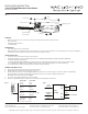
CONNECT THE WIRES: (FIG.2)
4. Remove appropriate power feed knockout in transformer box.
5. Bring building wires into knockout using cable connector.
6. Connect the electrical wires as shown in Fig. 2, making sure that all wire connectors (A1) are secured. To ultilize 0-10V dimming,
wire brown (dim+), blue (dim-), black (line hot), white (line neutral) in accordance to dimmer specications.
Green xture wire to ground as shown in Fig. 3.
7. Secure the cover (C1) by tightening the two screws (B1).
8. Connect compatible xture(s) to output wires of transformer following xture instructions.
Cover Screw
Wire Conduit
(not included)
Wire Connector
Cover
Mounting Screw
5 Pin Wire
B1
A1
C1
D1
E1
INSTALLATION INSTRUCTION
120V-277V 96W Electronic Transformer
EN-24100-277-RB2-T
HOT
(Black)
NEUTRAL
(White)
GROUND
(Green)
LED
DRIVER
Vout+
Vout-
dim+
dim-
Red
Black
Brown
Blue
LED
Module
0-10VDimmer