Installation and maintenance manual Closed circuit evaporative cooler Axial type Series RAA W-Tech S.r.l. Via Moglio, 18/2 - 40037 Sasso Marconi - (BO) Italy T: +39 051 6783010 F: +39 051 6784941 info@w-tech.it - www.w-tech.it Reg. Imp. BO C/F - P.Iva: 03079111203 - Rea BO 490312 - Cap. Soc. 32.000 € i.v.
TABLE OF CONTENTS 1. MACHINERY DESCRIPTION 1.1 General safety use 1.2 General description 1.3 Primary Circuit. 1.4 Secondary Circuit 1.4.1 Water pumping system 1.4.2 Water distribution system 1.5 Air induction system 1.6 Casing and water collection basin. 2 2. DELIVERY AND HANDLING Delivery Method 2.1 2.1.1 Lower body 2.1.2 Middle body (if any) 2.1.3 Upper body 2.2 Handling 4 4 4 4 4 4 3. INSTALLATION 3.1 Tower foundation and anchoring 3.2 Location conditions 3.3 Assembly of the bodies 3.
1. GENERAL SAFETY RULES AND MACHINERY DESCRIPTION 1.1 General Safety use: The content of this manual is to be considered as an integration to the general safety rules applied in your country, in the environment you are working in and also to the rules to be followed by law. In case of conflict with any of the previously mentioned rules in place, please contact our technical office for alternative procedures that will not create conflict.
1.6 Casing and water collection basin 2 The body of the unit is manufactured in “Sendzimir” galvanised steel covered with 300 g/m zinc layer. As a standard, a minimum 70µ complete paint of epoxy‐polyester layer is applied on each side of the panels. The application is done by electrostatic process, completed by a further one hour stop in to the oven. This is giving a considerable resistance against water corrosion, ultraviolet rays and other atmospheric elements.
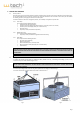
2. DELIVERY AND HANDLING 2.1 Delivery method All models of this series are delivered with the maximum possible elements mounted in our factory. Depending on the height of parts, the unit will be divided in order to lower the transport costs. Generally the deliveries are carried out in two or more parts. To facilitate the handling operation, the single parts are laid on a wooden pallet. Connection elements to be used on site (gaskets, silicone, nuts and bolts) are supplied in a separate box. 2.1.
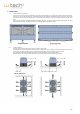
3. INSTALLATION 3.1 Tower foundation and anchoring Our units have no needs of any special foundation. They can be placed directly onto a concrete slab or onto concrete coated ground, making sure in all cases that the anchoring is capable of resisting the operating load distributed by the tower bed‐frame. They can be anchored on two steel beams, all along the basin. This anchoring can be observed in fig. 3 and will need some bolts and nuts to be fitted.
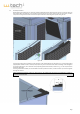
3.3 Assembly of the bodies Before beginning the assembly on site, check that all elements delivered inside the basin have been removed. To access the basin, the bolts used to capture the angle that is used to hold the louvers panels have to be eased. Then the angle is to be removed, as well as some panels. The angle to be removed is located in the adjacent side where the floating valve is placed. See fig. 6a e 6b. Fig.
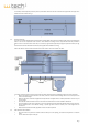
The assembly could he helped by means of pointers, which will be inserted in the holes in the lower body just before the upper one is allowed to rest on it. Please see fig. 7. Fig. 7 3.4 Electrical connection Our units are normally supplied with the electrical motors already cabled and the wires are available outside of the unit minimizing the labour on site. In case of particular motor versions or if the electrician is willing to re‐wire all, please find below the procedure to follow.
4. OPERATIONS TO BE CARRIED OUT BEFORE THE START UP 4.1 Cleaning • Make sure that the distribution system is clean and that the distribution nozzles are correctly positioned and free of any kind of blockage. • Check if the water basin is completely clean, if not, clean it using water under pressure. 4.2 Inspection and checking • Check the anchoring of the tower, the fans and motors and make sure they are correctly and securely tightened.
The following conditions must be maintained in order to eliminate them: • Ryznar index = 2 pHs ‐ pHc between 6 and 7. Where pHs is the pH of saturation and pHc is the true level measured in the circuit. • The product of sulphates and calcium concentration in the circuit water, (both expressed in mg/l Co3 Ca), should be less than 500,000. • Silica content should be lower than 150 mg/l. 6.2.1.2 Suspended solids.
7. GENERAL MAINTENANCE INSTRUCTIONS Due to the quality of these units, maintenance requirements are minimal. Nevertheless, they will be inspected fully on a monthly basis. In the same way, the entire circuit should be cleaned every year. It is advisable to carry out certain actions regularly in order to ensure that you achieve the service life and performance that these units have been designed for There are two basic areas to cover: 1. 2. Water recirculation system Air blowing system 7.
Fig. 10 7.1.6 7.2 Coil The coil has to be observed regularly. It has to be considered that this is a key element in the performance of the tower. Therefore, due to the possibilities of scaling, a monthly check is recommended and a daily purge of part of the spraying water. In the air flow system The airflow system does not require any special attention, due to its strength. Nevertheless, like any other moving element it has to be regularly checked, following the instructions below. 7.2.
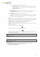
M M M CLEANING AND DISINFECTION M M/N M/N S/N S M S N S S M BASIN WATER LEVEL M INSPECTION FOR OVERHEATING, NOISE AND VIBRATION S/N INSPECTION FOR LEAKS M S/N S/N N TIGHTENING OF BOLTS AND ANCHORING N BALANCING AND ALIGNMENT N LUBRICATION (please check also the instruction manual of the suppliers) BLOWDOWN FLOW AND CONCENTRATION CYCLE CHECKING D = Every Day COLD WEATHER OPERATION M INSPECTION OF THE GENERAL CONDITION CASING M/N M INSPECTION FOR FOULING FAN DRIFT ELIMINATO
9. TROUBLESHOOTING CHART DEFECT POSSIBLE CAUSE ACTION TO BE TAKEN MOTOR ROTATES IN OPPOSITE DIRECTION Error in connection. Change two phases in the power supply to the motor. ABNORMAL VIBRATION IN MECHANICAL EQUIPMENT Fan / fan motor. Check state of blades and that they are correctly secured. Clean deposits from blades, eventually verify ice formation in winter. Check motor bolts and eventually tight.
Caratteristiche raccomandate acqua Recommended water charachteristic Caractéristiques de l’eau recommandées Minimale Wassereigenschaften Рекомендуемые характеристики воды Proprietà Property Propriété Eigenschaft Свойство Z-275 Galvanized steel Tôle en acier zingué Verzinkter Stahl Оцинкованная сталь AISI 304 Stainless Steel Acier Inoxydable Edelstahl Нержавеющая сталь AISI 316 Stainless steel Acier Inoxydable Edelstahl Нержавеющая сталь pH Solidi totali in sospensione (ppm) Total suspended solids (ppm)
W-Tech S.r.l. Management and Administration: Via Moglio 18/2 – 40037 Sasso Marconi (BO) – ITALY T: +39 051 6783010 F: +39 051 6784941 info@w-tech.it - www.w-tech.