
DCAM560C ToF Camera User Manual -20211210

15
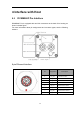
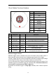
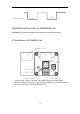
10 pin Multiple Functional Interface
Pin
Designation
1
VCC
2
VCC
3
GND
4
Ext_OUT
5
RS485-A
6
RS485-B
7
Ext_Trigger
8
Exposure_timing
9
GND
10
IP RESET
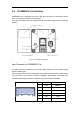
Pin
Designation
Direction
Description
1.2
VCC
Power
DC 12-24V
3.9
GND
GND
GND
4
Ext_OUT
OUTPUT
Control signal output from processor
5
RS485-A
I/O
RS485-A
6
RS485-B
I/O
RS485-B
7
Ext_Trigger
INPUT
External trigger input(3.3V-20V)
8
Exposure_timing
OUTPUT
Control signal output
10
IP RESET
INPUT
Pull high (3.3V-20V) for 10 seconds then the
IP is reset as 192.168.1.101.
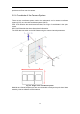
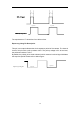
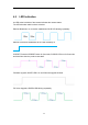
Hardware Trigger Function
Hardware trigger mode is available only when the camera works at slave mode, in
slave mode the camera will wait for the hardware trigger signal on Ext_Trigger.
The EXT_Trigger signal is to driver the MOSFET, External input trigger signal voltage
should range 3.3V-20V, driving current ability should be more than 5mA;
You can use input pin Ext_Trigger to send a hardware trigger signal to the camera. The
hardware trigger can be used to trigger the acquisition start. A hardware debouncer
circuit shall be considered on the EXT_Trigger line.
By default, the hardware trigger is rising edge activated, refer to below exposure
timing: