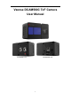
Vzense DCAM560C ToF Camera User Manual DCAM560C Pro DCAM560C Lite 1
Table of Contents 1 2 3 4 5 6 General Information ............................................................................................ 4 1.1 Terms of Use ............................................................................................ 4 Precautions ........................................................................................................ 5 2.1 Safe Usage Instructions ........................................................................... 5 2.2 Power ...............
6.2.2 Graphic Tool on windows.............................................................. 28 6.2.3 Frameviewer ................................................................................ 29 6.3 Firmware Upgrade.................................................................................. 29 6.4 Product State Machine ........................................................................... 30 6.5 Software Command Set .........................................................................
1 General Information The purpose of this document is to familiarize the customer with the correct operation of the Vzense ToF DCAM560C products family. This document provides important information about the camera’s features, hardware specification, safe use of the camera, and installation procedures. DCAM560C series have two configuration, DCAM560C Pro and DCAM560C Lite. DCAM560C Pro can be powered either by DC power or Power over Ethernet, and IP67 rating enclosure to resist dust and water.
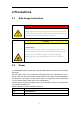
2 Precautions 2.1 Safe Usage Instructions DANGER Electric Shock Risk Non-standard and improper power supplies may result in fire and electric shock. You must confirm the camera power supply used that meets the Safety Extra Low Voltage(SELV) and Limited Power Supply (LPS) requirements. CAUTION Invisible Radiation This camera uses laser to work, improper use may damage the eye.
2.3 Usage Don’t try to open the camera housing. Each camera has been calibrated at the factory to achieve precise measurements. Touching internal components may damage the camera and cause calibration data lost. Incorrect plugging in and unplugging of the camera’s power cable can damage the camera. To avoid switch-on surges damaging the camera, please plug in the power cable into the camera’s 6-pin connector firstly before getting power supply.
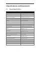
3 Specifications and Requirement 3.1 General Specifications Specification Vzense DCAM560C Technology ToF (Time-of-flight) Depth Camera Depth Sensor Resolution and Frame rate 640 x 480(VGA)@30FPS Output Formats Depth & IR Map (RAW12) Depth Sensor Field of View Typical: H-69°V-51° H-Horizontal, V-Vertical(degree) (customizable, up to H 120° V90°) RGB Sensor Resolution and Frame Rate 1600*1200@30fps RGB Sensor FOV H-77.6 °V-66.4° Use Range 0.
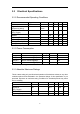
3.2 Electrical Specifications 3.2.1 Recommended Operating Conditions Parameter DC Power Digital I/O (Exposure_timing) Digital I/O (Ext_Trigger) RS485 Operating Temperature Operating humidity Storage humidity Storage temperature Symbol VDD Vout Conditions Min 11 Max 26 Units V V 3.3 20 V -12 -20 20 20 -30 12 50 80 80 70 V °C % % °C Work mode Vin Ta Typ. 12 5 3.2.
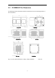
3.3 DCAM560C Pro Dimension This drawing contains information about the dimensions and user mounting location of the ToF Camera. Front View Back View Bottom View Top View Left View Right View Fig. 3.1: ToF Camera Dimensions: 105(L)×65(H)×59.
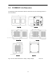
3.4 DCAM560C Lite Dimension This drawing contains information about the dimensions and user mounting location of the ToF Camera. Front View Back View Bottom View Top View Left View Right View Fig. 3.
3.5 Optical Specifications 3.5.1 Field of View The field of view refers to the view angle of the ToF products. The TOF sensor’s aspect ratio is 4:3, typically the horizontal field of view is larger than the vertical field of view. The DFOV (see figure below) is the angle subtended by the diagonal of the camera sensor onto the center of the lens. The definition of HFOV and VFOV can be exchanged, i. e. we can rotate the camera sensor to have larger FOV at vertical direction.
3.6 Working Condition Requirements 3.6.1 Hardware Requirements DCAM560C: ◼ CAT5 Ethernet cable (Included in package) ◼ 10 pin DC Power cable. (Included in package) Or ◼ PoE+ Power Supplier. (Not included in package) DCAM560C Lite: ◼ CAT5 Ethernet cable (Included in package) ◼ 6 pin cable which provide power and interface with host. (Included in package) ◼ DC Power cable. (Included in package) 3.6.
provide an air flow over the camera. 3.6.4 Coordinate of the Camera System There are two coordinate system need to be understood, one is camera coordinate system (CCS), one is world coordinate system (WCS). CCS: CCS describe the two-dimensional data, the origin of coordinates is the optic center. WCS: WCS describe the three-dimensional information. The CCS data can switch to the WCS data using the camera internal parameters. X Y Fig. 3.
4 Interface with Host 4.1 DCAM560C Pro Interface DCAM560C Pro is equipped with two M16 connectors at the back of its housing as shown in below figure. For more information about pin assignments and connector types, see the following sections.
10 pin Multiple Functional Interface Pin Designation 1 VCC 2 VCC 3 GND 4 Ext_OUT 5 RS485-A 6 RS485-B 7 Ext_Trigger 8 Exposure_timing 9 GND 10 IP RESET Pin Designation Direction Description 1.2 VCC Power DC 12-24V 3.9 GND GND GND 4 Ext_OUT OUTPUT Control signal output from processor 5 RS485-A I/O RS485-A 6 RS485-B I/O RS485-B 7 Ext_Trigger INPUT External trigger input(3.3V-20V) 8 10 Exposure_timing OUTPUT IP RESET INPUT Control signal output Pull high (3.
T1 T1 EXT_Trigger Exposure Exposure Camera Exposure The requirement to T1 should be from 100us to 2ms. Exposure_timing Pin Description This pin is an output indicates the whole exposure period of the camera. The internal circuit of this pin with a pull-up resistor 430Ω.The pull up voltage is 5V. At low level, the pull-down resistor is 100Ω. By default, the polarity is low level activated, which means a low-level signal indicates the exposure period.
4.2 DCAM560C Lite Interface DCAM560C Lite is equipped with RJ45, LED, 6pin connector, IP reset button at the back of its housing as shown in below figure. For more information about pin assignments and connector types, see the following sections. Fig. 4.2: Camera Connectors 6pin Connector for DCAM560C Lite The 6pin connector includes the one physical input signals and one physical output signal, RS485 signal. The pin assignments and pin numbering for the receptacle are as shown in below table.
Pin Description Pin Designation Direction Description 1 RS485-A I/O RS485-A 2 RS485-B I/O RS485-B 3 Ext_Trigger INPUT External trigger input(3.3V-20V) 4 Exposure_timing OUTPUT Control signal output 5 GND GND System ground 6 Ext_OUT OUTPUT Control signal output from processor Hardware Trigger Function Hardware trigger mode is available only when the camera works at slave mode, in slave mode the camera will wait for the hardware trigger signal on Ext_Trigger.
Exposure_timing Pin Exposure Exposure RJ45 Ethernet Connector for DCAM560C Lite DCAM560C Lite has the standard RJ45 interface for Ethernet transmission. IP Reset Button for DCAM560C Lite A hidden button hole is for IP reset, a pin shall be used to press the button. While the camera is powered on, long pressing the button for 10 seconds until the LED is off. Then the IP is reset as 192.168.1.101.
4.3 LED Indication An LED at the back side of the camera indicates the camera status. The LED animation table is shown as below: Ethernet Broadcast, no connection established, BLUE LED blinking repeatedly Ethernet connection established, BLUE LED constantly on IP RESET, Press the IP RESET button for 5 seconds, PURPLE LED is on for 5 seconds and blink twice then the product reset itself.
5 Principle of Time of Flight 5.1 Vzense ToF Principle Vzense DCAM710 product principle is based on range-gated imaging ToF solution, and the sensor inside is based on Panasonic CCD sensor MN34906. Fig. 9 5.2 Noise Factors 5.2.1 Ambient Light Because the ToF distance measurement relies on the reflection of light sent out by the camera, any additional light, e.g. artificial light sources or sunlight, may influence the measurement results.
To eliminate the multipath effect, you should: 1. Keep the camera working environment as clean as possible; 2. Avoid the camera be placed at concave forms environment, like corners of a room or inside of a narrow space; 3. Highly-reflective object shall be removed far away from the measurement target; 5.
6 Installation 6.1 Hardware Installation You have read and understood the warnings listed under "Precautions" on Chapter 2; To achieve reliable distance measurements, please follow below tips: ⚫ Better not using the camera in strong sunlight. If have to, keep the ambient light below 50k Lux. ⚫ Do NOT place any objects in the scene that are not part of your intended target, especially mirrors or other shiny surfaces/objects. ⚫ Maintain a stable housing temperature during operation.
1. Mount the camera in an appropriate fixture, e.g. a camera bracket; 2. Connect the DCAM560 Lite ToF camera to the host processor with the Ethernet cable(VZENSE-LAN-CAT5e-CABLE), the standard RJ45 socket locates at the back of the DCAM560 Lite camera; 3. Insert the DC connector of the power supply adaptor into the 12V DC Jack at the back of the camera; 4. Connect the adaptor to power source; 5. Please do set the IP address of the camera and host PC in the same segment; 6.
Why Use PoE? Specifying Power over Ethernet brings many advantages to an installation: Time and cost savings - by reducing the time and expense of having electrical power cabling installed. Network cables do not require a qualified electrician to fit them, and can be located anywhere. Flexibility - without being tethered to an electrical outlet, devices such as IP cameras and wireless access points can be located wherever they are needed most, and repositioned easily if required.
A midspan (or POE injector) is used to add POE capability to regular non-POE network links. Midspans can be used to upgrade existing LAN installations to POE, and provide a versatile solution where fewer POE ports are required. Upgrading each network connection to POE is as simple as patching it through the midspan, and as with POE switches, power injection is controlled and automatic. Midspans are available as multi-port rack-mounted units or low-cost single-port injectors.
4. Connect the PoE switch or PoE injector to power source; 6.1.4 Standalone Mode Installation This mode is for advanced users who require customization to the software and application, the applications can run on the processor inside the camera, and output the result data by either RS485 or EXT_OUTPUT pin. NRE fee shall be charged if you need Vzense team to do software or application customization.
6.2 Software Installation 6.2.1 How to get Download or clone SDK project from our GitHub /Gitee: China:https://gitee.com/Vzense Oversea:https://github.com/Vzense Please chose the suitable version based on the product and system. Windows SDK, Linux SDK have different project repository. 6.2.2 Graphic Tool on windows Vense uTool is a graphic tool on windows for the all Vzense ToF products. Download or clone uTool evaluation tool from our GitHub /Gitee: China:https://gitee.
6.2.3 Frameviewer Frameviewer is an opensource application in SDK project that can guide user how to call the SDK APIs. It has a pre-build version app in Tools folder, the source code is in Samples folder. See the document for the details. 6.3 Firmware Upgrade Download the VzenseUpgradeTool from below link: China: https://gitee.com/Vzense/VzenseUpgradeTool Oversea: https://github.com/Vzense/VzenseUpgradeTool Please read the Vzense_UpgradeTool_User_Guide.pdf before upgrading firmware.
6.4 Product State Machine ⚫ ⚫ ⚫ ⚫ ⚫ ⚫ 6.5 Power Off: product do not have any power Broadcast: broadcast IP address, socket have not connected Connected: socket is connected, product can transfer image and answer host command Factory Reset: resume all data to factory setting TOF Driver Upgrade: product is in upgrading of TOF driver System Upgrade: product is in upgrading of firmware Software Command Set DCAM560C support different work mode like depth_30, IR_30, depth&IR_30.
7 Features 7.1 Slave Trigger Mode At slave trigger mode, the DCAM560C product outputs image only at every trigger signal happens. Please refer to 4.1 6 Pin Connector for the requirement to the hardware trigger signal; Two ways can set the DCAM560C product at slave trigger mode: 1) Call API Ps2_SetSlaveModeEnabled(PsDeviceHandle device, uint32_t sessionIndex, bool bEnabled), before Ps2_StartStream(); This way requires calling the API every power cycle.
7.3 Wide Dynamic Range As mentioned above, Most of the ToF based 3D sensing technology has range limitation to nearest and furthest distance, due to the sensor saturation of weak light strength to far objects. One range mode of the Vzense DCAM560C camera can fulfill furthest distance be at most 5 times to nearest distance. For example, if the near limitation is 0.4m, then the furthest distance in this mode can reach about 2m. DISTANCE ERROR 0.025 0.02 0.015 0.01 0.
DISTANCE ERROR % Merge More Modes Into One 4 3.5 3 2.5 2 1.5 1 0.5 0 DISTANCE RANGE UNIT MM Please refer to Vzense_WDR_function_application_note.pdf implementation steps. 7.4 for the WDR Data Filtering In the software SDK and Frameviewer, we implemented data filtering to improve the depth data performance. The filtering algorithm includes: ⚫ Median filtering; ⚫ Gaussian filtering; ⚫ Bilateral filtering; ⚫ Timing filtering; ⚫ Flying pixel removing; 7.
8 Camera Operation on Frameviewer Please refer to 6.2.1 for the SDK downloading. Function 2D image show Camera hardware information show Image store Depth 30 IR 30 Mode Switch Depth&IR 30 WDR Range Change Range 0-7 Pulse count Exposure parameter modify Gamma gain Filters switch IR_BG 8.
8.1.1 Image area Image area is the area of showing depth image, IR image. 8.1.2 Command and information area Frameviewer use CMD shell for camera control and information output. Like the image below: switch mode, change detect range, save 3D image and so on.
8.2 Connect devices Frameviewer will auto-connect the device, and output the base information on the window. 8.3 2D view The display area can show different type image. 8.3.1 Depth Image Depth image is covert to a rainbow image for real distance showing.
8.3.2 IR Image 8.4 3D image store When the depth image is showing, input ‘s/S’ to store the point cloud file. User can use CloudCompare to viewer the 3D image.
8.5 Camera Control 8.5.1 Mode switch DCAM560C can support Depth_30, IR_30, Depth&IR_30. Depth_30: depth image only in 30 fps. IR_30: IR image only in 30 fps. Depth&IR_30: depth and IR image all in 30 fps. 8.5.2 Range change By default, DCAM560C product has 4 different range modes calibrated, please see below table for more information: Range number Distance range Range 0 0.35m~1.5m Range 1 0.5m~2.8m Range 2 0.8m~4.4m Range 5 1.2m~6.
customization, reasonable NRE fee will be charged. 8.6 WDR WDR mode can merge the multi-range image to extend the detect range. For example, if you want to get the distance from 0.35m to 4.4m, only one range mode can’t cover the whole distance. Use range 0 and 2 WDR can match this requirement. ⚫ Configure the WDR mode: ⚫ If you have some particular requirement and want to use WDR mode, you can contract with Vzense FAE first.
Depth image in range 0: Depth image in range 2: 41
Merged depth image in WDR mode 42
9 DCAM560C Accessories and Package In package item list: DCAM560C Pro Part No. Description DCAM560C Pro Vzense DCAM560C Pro Depth Camera Module VZENSE-LAN-CAT5eCABLE-8 Picture -CAT5e Ethernet Cable, 24AWG 4 Pair, shielded Twisted Pair; -Aviation Connector to RJ45 -Cord Length: 2m -9pin Multiple Functional Cable -Cord Length: 2m VZENSE-MFP-10P-A VZENSE-UG560C No.
-DC 12V~24V Input VZENSE-DC-A-CABLE -DC Plug: 5.5±0.1mm*2.1+0.1/-0mm*11.5±0.5mm -Cord Length: 2m -RED: DC 12V~24V input, BLACK: GND -6pin Multiple Functional Cable(RS485, EXT IO) -Cord Length: 1m VZENSE-MFP-6P-B VZENSE-UG560C No. Color Signal 1 BROWN RS485-A 2 GREEN RS485-B 3 WHITE Ext_Trigger 4 YELLOW Exposure_Timing 5 BLACK GND 6 RED Ext_OUT User guide You can ask Vzense to do customization to the cable for any reason, for example extending the cable length.
10 Customization Service Vzense team has rich experience in ToF product design and delivery, we welcome customer to send customization requirement besides the standard module. Reasonable NRE fee shall be charged depends on the requirement.