
User Manual


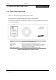
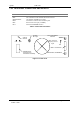
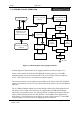
Table Of Contents

Vytek PTX-150
Doc Ref : 7M393-1 Version C1 Page : 7
VYTEK - 2000
3. INITIAL INSTALLATION
INSTALLATION
The following equipment will be required to test the transmitter: -
1. A good quality 50Ω dummy load or 30 dB high power attenuator suitable for 150W
continuous operation at 174 MHz and with a VSWR of better than 1.15:1.
2. A 486 or better PC with at least 8 Mbyte of RAM and one serial port, installed with
RDK software.
3. A suitable cable to connect the serial port of the PC to the dial Modem port of the
transmitter. Details of the required cable wiring are to be found in ‘CONNECTION
TO THE NETWORK’ section of the manual.
4. A suitable AC lead to suit the country where the transmitter is to be tested.
5. A ”Thruline” wattmeter fitted with the appropriate insert.
6. Suitable low loss RF cables and connectors.
Remove the VYTEK PTX-150 transmitter from its packing case and on a clean flat
surface, carefully examine the transmitter for physical damage. Pay particular attention to
the rear plugs and sockets. Verify that the rear cooling fan is free to rotate and does not
have packing material in it, which may prevent the blades from rotating.
Connect a good quality 50Ω dummy load rated for at least 150W continuous power at the
frequency of operation of the transmitter; to the transmitter RF output ”N” connector on
the rear panel.
WARNING: ATTEMPTING TO OPERATE THE TRANSMITTER
WITHOUT A PROPER LOAD CONNECTED TO THE RF
OUTPUT PORT WILL VOID THE WARRANTY.
The SONIK PTX-150 series Transmitters have a detailed and comprehensive test
sequence programmed in and this program activates immediately power is applied to
the unit.
• If the beeps and light sequencing occurs as specified, then all is well.
• If a dial Modem is connected, the start up sequence differs from that which would
occur if a dial Modem was not connected.
• With the transmitter located free of nearby objects which may block airflow through
the unit, switch on the transmitter by connecting the AC power cord to the AC supply
and operating the AC ON/OFF switch on the rear panel of the transmitter.