
User Manual

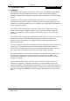
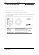
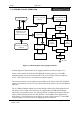
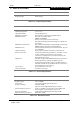
Table Of Contents

Vytek PTX-150
Doc Ref : 7M393-1 Version C1 Page : 2
VYTEK - 2000
1.2 INDICATORS AND CONNECTORS
INTRODUCTION
1.2.1 FRONT PANEL INDICATORS
Table 1.2.1 illustrates the front panel diagnostic LEDs.
Each LED shows the status of selected functions of the transmitter.
In the following figure, the ”CONSOLE” connector acts as the standard RS232 interface
for local programming.
LED FUNCTION
POWER Indicates that +24VDC is available from the Power supply.
TX ON Transmitter is transmitting RF power.
LOW POWER RF output is below alarm threshold set in software.
HIGH VSWR Antenna port matching is out of specifications set in software.
FAULT Global fault condition in the transmitter. Refer to ‘Trouble
shooting Guide’ in the handbook.
FRONT RS232 ACTIVE Indicates that the front panel RS232 port is in use.
Table1.2.1 LED indication of Transmitter status