
User Manual
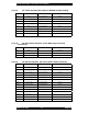
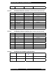
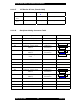

Table Of Contents
- FOREWORD
- GENERAL OVERVIEW
- SPECIFICATIONS
- ELECTRICAL REQUIREMENTS
- SITE PLANNING
- INSTALLATION
- OPERATION
- POWERING UP THE SYSTEM
- CONNECTING A TERMINAL
- Bootloader
- *************************
- G2BT BOOTLOADER
- Version 2F49405
- *************************
- Current MAC address = 00:01:02:03:04:05
- Current IP address = 11.31.3.4
- Current subnet = 255.255.255.128
- Current gateway = 11.31.3.126
- Current TFTP Server = 10.0.0.1
- Current Download File = g2bt.pkg
- ***You've got 5 seconds to escape normal boot process by entering any key...
- Loading application...
- Application
- QUICK-START CONFIGURATION
- SUBSYSTEMS
- USER INTERFACES
- SW DOWNLOAD PROCESS
- POWER CONTROL
- COMMAND LINE USER INTERFACE
- ALARMS AND MANAGEMENT
- FACTORY DEFAULT VALUES

Sonik G2BT Base Transmitter User Manual
March 14, 2002 39 7M487C4
12 POWER CONTROL
1
1
1
2
2
2
.
.
.
1
1
1
I
I
I
N
N
N
T
T
T
R
R
R
O
O
O
D
D
D
U
U
U
C
C
C
T
T
T
I
I
I
O
O
O
N
N
N
The power control function is designed to control keying and dekeying of the RF transmitter,
monitor the functionality and integrity of the exciter, power amplifiers, and the PA power
supplies, and operate the control loop that maintains the RF power output at the desired level.
1
1
1
2
2
2
.
.
.
2
2
2
C
C
C
O
O
O
N
N
N
F
F
F
I
I
I
G
G
G
U
U
U
R
R
R
A
A
A
T
T
T
I
I
I
O
O
O
N
N
N
M
M
M
O
O
O
N
N
N
I
I
I
T
T
T
O
O
O
R
R
R
I
I
I
N
N
N
G
G
G
The station power control and power output equipment is periodically monitored to ensure a safe
shutdown or cutback to a lower output power. The monitoring rate is every 100 mS. The RF
amplifiers themselves will not output power into an open load for more than about 100mS.
The user interface variable
pa installed
should be set to the number of power amplifiers present.
If 4 are present, the desired output power may be set to 400W, if 1 is present, the output power
may not exceed 100W. If 4 are present, but 1 or more cannot be operated, the output power will
be automatically reduced as detailed in the power cutback and transmitter de-key section below.
The number of available PAs can be determined from the internal monitoring functions of the
PAs, which allow supply voltage, supply current, temperature, fan status, and power output be
measured. In the event of a problem, the gain of the PA can be reduced, or it can be shut down
entirely.
The exciter card is monitored to determine that the IF and RF synthesizer LOs are operating and
locked.
The integrity of the system output devices and cabling is determined by measuring forward and
reflected power at the 4 PA internal wattmeters and the system wattmeter.
1
1
1
2
2
2
.
.
.
3
3
3
P
P
P
O
O
O
W
W
W
E
E
E
R
R
R
C
C
C
O
O
O
N
N
N
T
T
T
R
R
R
O
O
O
L
L
L
A
A
A
L
L
L
G
G
G
O
O
O
R
R
R
I
I
I
T
T
T
H
H
H
M
M
M
The G2BT can be configured as either a high power station, transmitting a maximum of 400 watts
when fitted with 4 PAs, or as a low-power station transmitting a maximum of 100 watts when
configured with 1 PA. The desired power level may be selected by the user in the range 100W to
400W for the high power station, and 25W to 100W for the low power station. The station may
also cut back the output power as a response to fault conditions such as overheating.