
User Manual
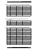
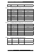
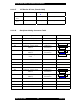
Table Of Contents
- FOREWORD
- GENERAL OVERVIEW
- SPECIFICATIONS
- ELECTRICAL REQUIREMENTS
- SITE PLANNING
- INSTALLATION
- OPERATION
- POWERING UP THE SYSTEM
- CONNECTING A TERMINAL
- Bootloader
- *************************
- G2BT BOOTLOADER
- Version 2F49405
- *************************
- Current MAC address = 00:01:02:03:04:05
- Current IP address = 11.31.3.4
- Current subnet = 255.255.255.128
- Current gateway = 11.31.3.126
- Current TFTP Server = 10.0.0.1
- Current Download File = g2bt.pkg
- ***You've got 5 seconds to escape normal boot process by entering any key...
- Loading application...
- Application
- QUICK-START CONFIGURATION
- SUBSYSTEMS
- USER INTERFACES
- SW DOWNLOAD PROCESS
- POWER CONTROL
- COMMAND LINE USER INTERFACE
- ALARMS AND MANAGEMENT
- FACTORY DEFAULT VALUES

Sonik G2BT Base Transmitter User Manual
March 14, 2002 38 7M487C4
The G2BT contains Flash memory to store two complete images of the software download
file (i.e. two complete images of each of the binary images for the SCM software, the DSP
software and the FPGA configuration code). One virtual Flash memory bank contains a copy
of the currently active software images, the other virtual Flash memory bank contains a copy
of a dormant set of binary images. The SCM controls this information by storing several
small arrays of software download status in the EEPROM.
The arrays in EEPROM contain the following information:
•
FlashBank[active, dormant] =
virtual bank 1
|
virtual bank 2
•
Version[active | dormant ] [SCM | DSP | FPGA | Loader | Revert] =
version
The software download file is decoded, verified for platform and data integrity and then
written to the dormant virtual Flash memory bank. The Version[dormant][] array is updated
with the version values of the SCM, DSP and FPGA binary images as written in the software
download file.
1
1
1
1
1
1
.
.
.
3
3
3
C
C
C
U
U
U
T
T
T
O
O
O
V
V
V
E
E
E
R
R
R
T
T
T
O
O
O
T
T
T
H
H
H
E
E
E
N
N
N
E
E
E
W
W
W
V
V
V
E
E
E
R
R
R
S
S
S
I
I
I
O
O
O
N
N
N
O
O
O
F
F
F
D
D
D
O
O
O
W
W
W
N
N
N
L
L
L
O
O
O
A
A
A
D
D
D
E
E
E
D
D
D
S
S
S
O
O
O
F
F
F
T
T
T
W
W
W
A
A
A
R
R
R
E
E
E
The software binaries remain in the Flash memory as dormant until actively specified to be
cutover.
First the user specifies which version to cutover to through the user interface or through
SNMP MIB sets. The system verifies that these are valid versions. If valid, the SCM updates
the arrays in EEPROM to reflect the user specified versions. The actual cutover does not yet
occur.
Then the user activates the cutover process through the user interface or through SNMP MIB
sets. The activation can be
NOW
or
TIMED
(scheduled) depending on command parameters.
The system verifies that the specified cutover version(s) is different from the current active
version. This prevents unnecessary cutovers. If the cutover version(s) is different from the
active current version, the system disables paging, turns off all interrupts thereby halting all
network and front panel activity, and performs a warm CPU reset.
At reset, the boot loader loads the active SCM software into RAM and begins execution. The
SCM software sends the active FPGA configuration code to the FPGA and the active DSP
code to the DSP.