
User Manual
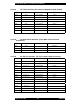
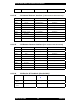
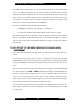
Table Of Contents
- FOREWORD
- GENERAL OVERVIEW
- SPECIFICATIONS
- ELECTRICAL REQUIREMENTS
- SITE PLANNING
- INSTALLATION
- OPERATION
- POWERING UP THE SYSTEM
- CONNECTING A TERMINAL
- Bootloader
- *************************
- G2BT BOOTLOADER
- Version 2F49405
- *************************
- Current MAC address = 00:01:02:03:04:05
- Current IP address = 11.31.3.4
- Current subnet = 255.255.255.128
- Current gateway = 11.31.3.126
- Current TFTP Server = 10.0.0.1
- Current Download File = g2bt.pkg
- ***You've got 5 seconds to escape normal boot process by entering any key...
- Loading application...
- Application
- QUICK-START CONFIGURATION
- SUBSYSTEMS
- USER INTERFACES
- SW DOWNLOAD PROCESS
- POWER CONTROL
- COMMAND LINE USER INTERFACE
- ALARMS AND MANAGEMENT
- FACTORY DEFAULT VALUES

Sonik G2BT Base Transmitter User Manual
March 14, 2002 31 7M487C4
9.1.1.11 J17 Telco Interface (8 Conductor Modular Keyed Socket)
PIN FUNCTION DIRECTION CONNECTS TO
J24P1 SIG1 Programmable J25P73
J24P2 SIG2 Programmable J25P74
J24P3 SIG3 Programmable J25P75
J24P4 SIG4 Programmable J25P76
J24P5 SIG5 Programmable J25P77
J24P6 SIG6 Programmable J25P78
J24P7 SIG7 Programmable J25P79
J24P8 SIG8 Programmable J25P80
9.1.1.12 J20 Door Alarm Interface (3 Pin Male Snap and Lock
Connector)
PIN FUNCTION DIRECTION CONNECTS TO
J20P1 GND Backplane
J20P2 DOOR_ALM To Backplane J4-P25
J20P3 GND Backplane
9.1.1.13 J21 PA SPI Interface (15 Pin Female D Sub Connector)
PIN FUNCTION DIRECTION CONNECTS TO
J17P1 GND To Backplane Backplane
J17P2 PA_SPI_A5 From Backplane J4-P65
J17P3 PA_SPI_A4 From Backplane J4-P66
J17P4 PA_SPI_A3 From Backplane J4-P67
J17P5 PA_SPI_A2 From Backplane J4-P68
J17P6 PA_SPI_A1 From Backplane J4-P64
J17P7 PA_SPI_A0 From Backplane J4-P63
J17P8 PA_SPI_CLK From Backplane J4-P77
J17P9 PA_SPI_MOSI From Backplane J4-P78
J17P10 PA_SPI_MISO To Backplane J4-P75
J17P11 Not used
J17P12 Not used
J17P13 Not used
J17P14 Not used