
User Manual
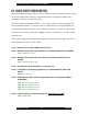
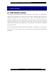
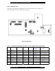
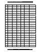
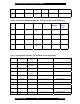
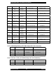
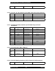
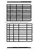
Table Of Contents
- FOREWORD
- GENERAL OVERVIEW
- SPECIFICATIONS
- ELECTRICAL REQUIREMENTS
- SITE PLANNING
- INSTALLATION
- OPERATION
- POWERING UP THE SYSTEM
- CONNECTING A TERMINAL
- Bootloader
- *************************
- G2BT BOOTLOADER
- Version 2F49405
- *************************
- Current MAC address = 00:01:02:03:04:05
- Current IP address = 11.31.3.4
- Current subnet = 255.255.255.128
- Current gateway = 11.31.3.126
- Current TFTP Server = 10.0.0.1
- Current Download File = g2bt.pkg
- ***You've got 5 seconds to escape normal boot process by entering any key...
- Loading application...
- Application
- QUICK-START CONFIGURATION
- SUBSYSTEMS
- USER INTERFACES
- SW DOWNLOAD PROCESS
- POWER CONTROL
- COMMAND LINE USER INTERFACE
- ALARMS AND MANAGEMENT
- FACTORY DEFAULT VALUES

Sonik G2BT Base Transmitter User Manual
March 14, 2002 25 7M487C4
9.1.1 CE B
ACKPLANE
The G2BT Control Equipment Backplane has the I/O connections for the CE chassis. The
following diagram shows the location of the connectors.
J21
J23
J12
J7
J14
J13
J20
J15
J8
J17
J27
J26
J10
J22
J11
J9
G2BT CE Backplane
9.1.1.1 J7 External Controller Interface (37 Pin Female D Sub Connector)
PI
N
PnP/xTIP I-20 SatRX SyLC SCM NET
NAMES
CONNECTS
TO
J7
P1
SHIELD GND GND GND Backplane
J7
P2
RFC MAINT A R(A) AsyncRXD
+
AsyncRX
D+
MODEM_TX
DA
J3-P58, J16-P2, J25-P2
J7
P3
TX MAINT A T(A) AsyncTXD
+
AsyncTX
D+
MODEM_RX
DA
J3-P62, J16-P3, J25-P3
J7
P4
PT DATA A I(A) DTA+ DATA RS485_D+ J4-P37, J6-P41
J7
P5
PT FRAME A C(A) DCD+ KEY+ DIST_DCD J4-42, J6-P50
J7
P6
Wildcard out 1 Wildcard out 1 Wildcard
out 1
J7
P7
SGND GND GND GND Backplane
J7
P8
MARK A B(A) Wildcard
in 2+
BAUD MODEM_DC
DA
J3-P73, J16-P8, J25-P8