
User Manual
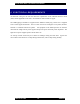
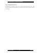
Table Of Contents
- FOREWORD
- GENERAL OVERVIEW
- SPECIFICATIONS
- ELECTRICAL REQUIREMENTS
- SITE PLANNING
- INSTALLATION
- OPERATION
- POWERING UP THE SYSTEM
- CONNECTING A TERMINAL
- Bootloader
- *************************
- G2BT BOOTLOADER
- Version 2F49405
- *************************
- Current MAC address = 00:01:02:03:04:05
- Current IP address = 11.31.3.4
- Current subnet = 255.255.255.128
- Current gateway = 11.31.3.126
- Current TFTP Server = 10.0.0.1
- Current Download File = g2bt.pkg
- ***You've got 5 seconds to escape normal boot process by entering any key...
- Loading application...
- Application
- QUICK-START CONFIGURATION
- SUBSYSTEMS
- USER INTERFACES
- SW DOWNLOAD PROCESS
- POWER CONTROL
- COMMAND LINE USER INTERFACE
- ALARMS AND MANAGEMENT
- FACTORY DEFAULT VALUES

Sonik G2BT Base Transmitter User Manual
March 14, 2002 16 7M487C4
6 INSTALLATION
6
6
6
.
.
.
1
1
1
C
C
C
A
A
A
B
B
B
I
I
I
N
N
N
E
E
E
T
T
T
G
G
G
R
R
R
O
O
O
U
U
U
N
N
N
D
D
D
I
I
I
N
N
N
G
G
G
Safety and operation depends on proper grounding of the equipment. The main cabinet ground is
on the top of the cabinet, as shown in the following diagram. The main cabinet ground connects
to the cabinet rail, and each chassis installed in the cabinet has an independent ground.
Locate the site ground wire and connect it to the cabinet as follows:
Note: The site ground wire must be AWG #2 or larger, green-insulated solid copper wire.
1. Strip 3/8 of an inch of wire from the end of the ground wire.
2. Loosen the set-screw on the ground connetion to the transmitter and insert the stripped end of
the wire under it.
3. Leave approximately 1/16 of an inch of bare-wire exposed outside the grounding connection.
4. Tighten the set-screw to secure the ground wire to the ground of the transmitter.
5. Ensure that the other end of the ground wire is properly connected to the site ground system.
6
6
6
.
.
.
2
2
2
A
A
A
N
N
N
T
T
T
E
E
E
N
N
N
N
N
N
A
A
A
C
C
C
O
O
O
N
N
N
N
N
N
E
E
E
C
C
C
T
T
T
I
I
I
O
O
O
N
N
N
S
S
S
6.2.1 GPS
The GPS antenna connection is a type N connection on the top of the unit. Locate and connect
the GPS antenna cable to the GPS N connector, and tighten it securely.
CAUTION!
The transmitter supplies +5Vdc power to the antenna using the coax center pin. If you use a GPS
antenna with a DC short to ground, you must install a DC block in-line with the antenna coax
cable
.